02/23/2021 11,665 VAZ
Author: Ivan Baranov
To ensure normal engine starting in any weather, many different mechanisms and elements are used. But they are all combined into one system - the ignition system (I). We will tell you more about the SZ for the Oka car below. What functions does the Oka ignition coil perform, what malfunctions are typical for SZ in general, and how to set the advance angle - read below.
[Hide]
Ignition Features
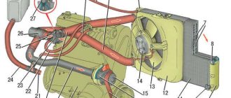
Diagram of a contactless SZ on the Oka
Before we talk about how to set and adjust the ignition on the Oka with your own hands in accordance with the diagram, let's understand the features of the SZ.
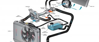
The ignition system on any car includes several different components, the main ones:
- Spark timing controller. This device is equipped with vacuum and centrifugal regulators. The device is designed to ensure the timing of spark formation, taking into account its standard installation, the number of engine revolutions, and the load on the motor. The signal reading procedure is based on the Hall effect.
- The switching device is designed to open the supply circuit of the primary winding of the short circuit, thus converting control signals into current pulses. When the ignition is activated, the connector of the switching device must not be disconnected under any circumstances, since this will lead to damage not only to this unit, but also to other elements of the SZ.
- Coil. In the ignition systems of Oka cars, in accordance with the diagram, a two-terminal short circuit with an open or closed magnetic circuit is used.
- Candles. This element is designed to transmit a high-voltage pulse, which contributes to the ignition of the combustible mixture in the cylinders of the internal combustion engine. The service life of spark plugs is about 10 thousand km, but this figure can be changed upward in accordance with the specifics of the spark plugs themselves. Or to a lesser extent, if for some reason the service life of the spark plugs is reduced.
- High-voltage cables designed to connect spark plugs to a distributor. In Oka, high-voltage circuits with distributed resistance are used. Do not touch them while the engine is running, as this may cause serious injury. It is also prohibited to start the power unit if the high-voltage circuit is broken (the wires may be broken or crushed, or the insulation on them may be damaged). If the insulation is broken, then other elements of the system may fail in accordance with the diagram.
- Egnition lock. According to the diagram, the lock is designed to start the engine by supplying voltage to an additional relay when the key is turned (video author - Nail Poroshin).
Typical system malfunctions
Among the malfunctions of the SZ, the following should be highlighted:
- Coil failure. This problem doesn't happen often, but it can happen nonetheless.
- Distributor failure. You can read more about distributor malfunctions, as well as troubleshooting, here.
- Spark plugs are worn out or have carbon deposits on them. This problem is relevant for many of our compatriots. Read about the reasons why soot appears and what ways to eliminate this problem exist in this article.
- Malfunction of high-voltage wires. The wires may be broken (broken) or their insulation may be damaged. Operating a car with such a problem is not allowed.
- Broken ignition switch. Wear on the inside of the lock will result in the driver being unable to start the engine with the existing key. Replacing the lock cylinder will solve the problem (the author of the video is Mikhail Burashnikov).
Malfunctions
The simplified design of the ignition system and the absence of moving components ensures high reliability and ease of maintenance.
There are not so many malfunctions in the Oka ignition system:
- Switch failure;
- Hall sensor malfunction;
- Coil failure;
- Breakage or breakdown of wires, oxidation of contacts;
- Spark plug malfunction;
- Violation of the ignition timing;
Since the ignition system is directly involved in the operation of the engine, any malfunction in it immediately affects the performance of the engine - interruptions occur, the unit does not develop power, popping noises appear, or the unit simply does not start.
Diagnosis of a malfunction is carried out by visual inspection of the wiring and its connections, as well as by sequentially replacing all components with known good ones. A check using measuring instruments allows you to more accurately determine the faulty element.
The search for the problematic element is carried out from the candles. That is, first the presence of a spark is checked on them, then the high-voltage wires are inspected, and then the performance of the coil, switch, and Hall sensor is diagnosed.
The components of the ignition system are non-repairable, so if they break down they must be replaced.
Ignition installation instructions
How to set the lead angle correctly:
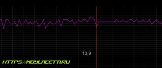
- First of all, you need to open the hood and remove the air filter. The angle diagnostic procedure should be carried out at idle engine speed, while the crankshaft should operate at a frequency of about 850-900 rpm. The angle itself can be deviated from TDC by no more than one degree. If it is set incorrectly, the motor may overheat, and the machine as a whole will not be able to develop the required power. Depending on the car, the problem may also cause detonation.
- To prevent the set ignition angle from leading to such consequences, you first need to align the mark on the flywheel of the internal combustion engine with the middle mark on the scale. The first mark is located on the flywheel itself, the second is on the scale of the crankshaft rear oil seal. At this moment, the piston in the cylinder will be located at TDC. When setting, keep in mind that each division corresponds to two degrees of the crankshaft gate.
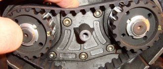
- In addition, the ignition adjustment procedure can be carried out taking into account the marks located on the generator drive pulley and on the timing belt protective cover. The longest mark should correspond to the installation of the piston of cylinder 1 in the TDC position. As for the short mark, it corresponds to a five-degree advance of the crankshaft rotation.
- You need to disconnect the pipe connected to the vacuum regulator. Having done this, you can disconnect the high-voltage cable from the spark plug installed in cylinder 1. This wire will subsequently need to be connected to the strobe - before use, read the service book of the device.
- After completing these steps, you need to remove the rubberized plug from the clutch housing hatch. The luminous flux should be directed into the crankcase hatch itself. If the angle is set correctly, the mark will be between marks 2 and 3.
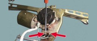
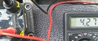
- Next, using a wrench, you need to loosen the three nuts that secure the spark sensor. If you need to increase the torque, then the controller should be turned clockwise, respectively, if you decrease it, then counterclockwise. When the adjustment is complete, the nuts will need to be tightened.
Common faults
All malfunctions in the wiring on the VAZ 2111 Oka can be divided into several groups:
- Failure of the device itself. For example, if we are talking about headlights, then the lamps in them may burn out. If the rear window heating system refuses to work, then the unit itself may be faulty.
- Broken electrical wiring. As a rule, this problem is more relevant for wires that are laid in places where there are moving or rubbing elements. For example, wires from door locks are laid in the doors themselves, and to connect to the fuse box they are laid in special rubber corrugations. Despite such protection, wires can also break in the corrugation.
- No contact. The lack of contact may be due to either a broken wire or oxidation of the contact; in some cases, it may simply move away from the installation socket. In case of oxidation, the problem is solved by stripping.
- The fuse or relay has blown. This happens especially often in cars where there are power surges. The fuse simply cannot withstand the power of the on-board network and fails, thus protecting the device from burnout. If your car actually has power surges, then you need to either check the on-board network yourself or contact an electrician.
- Also one of the most common malfunctions is battery discharge. Car owners usually face this problem with the onset of cold weather; in some cases, it may be due to improper maintenance (the author of the video is the Milin0915 channel).
Treatment of joints
To ensure normal engine starting in any weather, many different mechanisms and elements are used. But they are all combined into one system - the ignition system (I). We will tell you more about the SZ for the Oka car below. What functions does the Oka ignition coil perform, what malfunctions are typical for SZ in general, and how to set the advance angle - read below.
Contactless SZ scheme on Oka
Before we talk about how to set and adjust the ignition on the Oka with your own hands in accordance with the diagram, let's understand the features of the SZ.
The ignition system on any car includes several different components, the main ones:
- Spark timing controller. This device is equipped with vacuum and centrifugal regulators. The device is designed to ensure the timing of spark formation, taking into account its standard installation, the number of engine revolutions, and the load on the motor. The signal reading procedure is based on the Hall effect.
- The switching device is designed to open the supply circuit of the primary winding of the short circuit, thus converting control signals into current pulses. When the ignition is activated, the connector of the switching device must not be disconnected under any circumstances, since this will lead to damage not only to this unit, but also to other elements of the SZ.
- Coil. In the ignition systems of Oka cars, in accordance with the diagram, a two-terminal short circuit with an open or closed magnetic circuit is used.
- Candles. This element is designed to transmit a high-voltage pulse, which contributes to the ignition of the combustible mixture in the cylinders of the internal combustion engine. The service life of spark plugs is about 10 thousand km, but this figure can be changed upward in accordance with the specifics of the spark plugs themselves. Or to a lesser extent, if for some reason the service life of the spark plugs is reduced.
- High-voltage cables designed to connect spark plugs to a distributor. In Oka, high-voltage circuits with distributed resistance are used. Do not touch them while the engine is running, as this may cause serious injury. It is also prohibited to start the power unit if the high-voltage circuit is broken (the wires may be broken or crushed, or the insulation on them may be damaged). If the insulation is broken, then other elements of the system may fail in accordance with the diagram.
- Egnition lock. According to the diagram, the lock is designed to start the engine by supplying voltage to an additional relay when the key is turned (video author - Nail Poroshin).
Typical system malfunctions
Among the malfunctions of the SZ, the following should be highlighted:
- Coil failure. This problem doesn't happen often, but it can happen nonetheless.
- Distributor failure. You can read more about distributor malfunctions, as well as troubleshooting, here.
- Spark plugs are worn out or have carbon deposits on them. This problem is relevant for many of our compatriots. Read about the reasons why soot appears and what ways to eliminate this problem exist in this article.
- Malfunction of high-voltage wires. The wires may be broken (broken) or their insulation may be damaged. Operating a car with such a problem is not allowed.
- Broken ignition switch. Wear on the inside of the lock will result in the driver being unable to start the engine with the existing key. Replacing the lock cylinder will solve the problem (the author of the video is Mikhail Burashnikov).
Ignition installation instructions
How to set the lead angle correctly:
- First of all, you need to open the hood and remove the air filter. The angle diagnostic procedure should be carried out at idle engine speed, while the crankshaft should operate at a frequency of about 850-900 rpm. The angle itself can be deviated from TDC by no more than one degree. If it is set incorrectly, the motor may overheat, and the machine as a whole will not be able to develop the required power. Depending on the car, the problem may also cause detonation.
- To prevent the set ignition angle from leading to such consequences, you first need to align the mark on the flywheel of the internal combustion engine with the middle mark on the scale. The first mark is located on the flywheel itself, the second is on the scale of the crankshaft rear oil seal. At this moment, the piston in the cylinder will be located at TDC. When setting, keep in mind that each division corresponds to two degrees of the crankshaft gate.
- In addition, the ignition adjustment procedure can be carried out taking into account the marks located on the generator drive pulley and on the timing belt protective cover. The longest mark should correspond to the installation of the piston of cylinder 1 in the TDC position. As for the short mark, it corresponds to a five-degree advance of the crankshaft rotation.
- You need to disconnect the pipe connected to the vacuum regulator. Having done this, you can disconnect the high-voltage cable from the spark plug installed in cylinder 1. This wire will subsequently need to be connected to the strobe - before use, read the service book of the device.
- After completing these steps, you need to remove the rubberized plug from the clutch housing hatch. The luminous flux should be directed into the crankcase hatch itself. If the angle is set correctly, the mark will be between marks 2 and 3.
- Next, using a wrench, you need to loosen the three nuts that secure the spark sensor. If you need to increase the torque, then the controller should be turned clockwise, respectively, if you decrease it, then counterclockwise. When the adjustment is complete, the nuts will need to be tightened.
Wiring diagram SeAZ VAZ-11116
in high resolution (1 MB).
1/1 — High beam headlights; 1/2 — Low beam headlights; 1/4 — Side light lamp; 2 — Front direction indicator lamp; 3 — Side direction indicator lamp; 5 — Generator with built-in voltage regulator; 9 — Hall sensor; 10 - Ignition coil; 12 — Starter Lada Oka; 13 - Spark plugs; 14 — Sound signaling device; 17 - Water temperature indicator sensor; 18 - Oil pressure warning lamp sensor; 23 - Battery; 25 - Reversing lamp switch; 26 - Brake light switch; 30 — Relay-breaker of direction indicators; 31 — Relay-breaker for the handbrake warning lamp; 32 - Windshield wiper relay; 33 - Additional resistance of the heater electric motor; 35 - Windshield wiper motor; 37 - Electric heater motor; 38 — Radiator cooling fan electric motor; 39 - Electric fan relay; 42/1 — Turn indicator switch; 42/2 — Headlight switch; 42/3 — Windshield wiper and washer switch; 42/4 - Switch for sound warning device; 44 - Ignition switch; 46 — External lighting switch; 48 - Hazard switch; 49 - Heater motor switch; 52 - Instrument cluster; 63 — Speed sensor Lada Oka; 74/1 — Thermal cigarette lighter element; 74/2 — Cigarette lighter lamp; 75 — Brake fluid level sensor; 76 - Handbrake warning lamp switch; 77 — Diagnostic block; 81 — Cartridge for connecting a portable lamp; 83 - Windshield washer pump; 87 — Interior lighting switch in the front door; 89 — Interior lamp; 93 — Sensor for level indicator and fuel reserve; 98/1 — Side light lamp; 98/2 — Turn signal lamp; 98/3 — Brake light lamp; 98/4 - Reversing lamp; 99 — License plate lamp; 104 - Electric fan thermal switch; 108 — Rear fog lamp; 112 - Rear window wiper motor; 113 — Rear window washer motor; 115 — Rear window heating element; 121 — Relay for turning on the heated rear window; 125 - Additional relay; 126 - Relay for high beam headlights; 127 - Relay for low beam headlights; 129 - Starter relay; 133 — Rear window heating switch; 136 — Rear fog lamp switch; 137 - Rear window wiper switch; 138 — Rear window washer switch; 158 - Fuel injectors; 159 — OKA watch; 168 — Relay for rear fog lights; 169 - Additional brake signal; 170 - Fuel pump relay; 171 - Electric fuel pump; 172 - Idle speed regulator; 173 - Throttle position sensor; 174 - Knock sensor; 175 - Canister purge valve; 176 - Oxygen sensor; 177 - Absolute pressure sensor; 178 - Main relay; 221 - Controller.
Useful: Pinout and diagram of a fuel pump with a VAZ relay