Troubleshooting if turns do not work, even if you do not have special knowledge.
Checking the serviceability of the turn relay.
And so let’s look at what to do if the turns of a front-wheel drive VAZ, except for the 2170 Priora, do not work. The operation and troubleshooting of which was discussed in the article “Prior Turning Relay”.
First, make sure that the measuring instruments and control lamps on the instrument panel are working. If they do not work, then check the fuse.
If the devices are working properly, turn on the hazard warning button and check that all the lamps in the direction indicators are blinking. This will allow you to divide the circuit into two parts and speed up troubleshooting.
If the alarm does not work when turned on, then it is necessary to check the serviceability of the turn and alarm relay and the presence of power at its terminal 49. The pin designation is marked on the bottom of the relay, next to the contact legs.
We remove the relay, which is marked in the form of a triangle on the top of the case, from the mounting block, and in the vacated socket, using a test paw, check for the presence of a plus on pin 49. We connect the test lamp to the ground or minus of the battery, and with the other end we touch pin 49, when If the hazard warning button is on, you do not need to turn on the ignition. Lack of power indicates a faulty fuse, alarm button or broken wires, contact tracks of the mounting block and poor contact in the connectors.
If there is a plus on the terminal, then connect terminals 49 and 49A with a copper wire. If the connecting wires and connectors are in good condition, all the direction indicator lamps should light up. This indicates that the turn signal and light signaling relay is faulty. If the lamps do not light up, but there is a plus on pin 49, then there may be a short circuit in the signal lamp circuit and the fuse has blown. A short circuit can also cause the relay to fail. In this case, check the serviceability of the fuse, and if it blows, eliminate the short circuit in the signal lamp circuit.
Checking the hazard warning button.
If the hazard warning lights are working, then the turn signal and hazard warning relays are working properly, but the fault may be in the hazard warning light button. First, check the plus, as described earlier at pin 49 of the relay, with the hazard warning button off and the ignition on.
If there is no plus, then you need to check the serviceability of the alarm button. To do this, you need to remove the button from the socket by prying it off with a thin screwdriver or remove the instrument panel visor. In the contact connector of the button, use a test lamp to check the presence of power at pin 2 (the numbering of pins on the button near the contacts) with the ignition on. If there is no power, repair the broken wire from the instrument panel to the button. If there is power, connect pin 2 to pin 5 in the button socket, with the ignition on, and turn on the direction indicators of either side. If the warning lights on this board light up, replace the faulty hazard warning button.
If the warning lights do not light up, then, without removing the jumper from the hazard warning button block, connect pins 49 and 49A with a copper wire in the relay socket, then check the power at pin 49A of the turn switch. To do this, remove the steering column cover and the connecting connector from the turn switch. You can also remove the switch itself to determine the pin numbers that are marked on its lower part next to the contact legs. This is not difficult to do by squeezing the latches on the sides of the switch and pulling it to the side. If the circuit from the relay to the switch is in good condition, the indicator lamp will start to light. If the control lamp does not light, then repair the break in the wire from the mounting block to the turn signal connector.
Checking the serviceability of the turn relay.
None First, make sure that the gauges and warning lights on the instrument panel are working. If they do not work, then check the fuse.
If the devices are working properly, turn on the hazard warning button and check that all the lamps in the direction indicators are blinking. This will allow you to divide the circuit into two parts and speed up troubleshooting. If the alarm does not work when turned on, then it is necessary to check the serviceability of the turn and alarm relay and the presence of power at its terminal 49. The pin designation is marked on the bottom of the relay, next to the contact legs.
We remove the relay, which is marked in the form of a triangle on the top of the case, from the mounting block, and in the vacated socket, using a test paw, check for the presence of a plus on pin 49. We connect the test lamp to the ground or minus of the battery, and with the other end we touch pin 49, when If the hazard warning button is on, you do not need to turn on the ignition. Lack of power indicates a faulty fuse, alarm button or broken wires, contact tracks of the mounting block and poor contact in the connectors.
When turning on the turns, the fuse blows.
Another malfunction of the direction indicators is the fuse blowing when the indicators of one of the sides are turned on. To quickly identify a malfunction, turn on the hazard warning lights. The signal lamp in a circuit that has a short circuit will not light up or will burn at full intensity. A sign of a short circuit in the signal lamp circuit can be a buzzing sound from the turn signal relay when the indicators are turned on. To facilitate troubleshooting when the VAZ direction indicators do not work, use the diagrams below.
Reasons for failure of turn signals and emergency lights
As you know, the circuit of direction indicators and hazard warning lights is tied, since both functions are performed by the same headlights. If for some reason the hazard lights are working, but the turn signals are not, or neither the turns nor the warning lights are on, this can lead to an emergency situation on the road.
For what reasons did these elements stop working:
- Fuse failure is one of the most common problems. If the car is additionally equipped with a relay that is responsible for the operation of these optical elements, then the problem may lie there. Depending on the car model, the relay may be located separately from the main fuse block; use the diagram to find the failed part.
- Short circuit in the system. Because of this, when turning on the turning lights, the emergency lights turn on or the optics do not respond to the driver’s commands at all. To diagnose the problem, you will need a tester, as well as the skills of an electrician.
- Failure of the lighting source. In other words, the light bulb has burned out.
- Open circuit. This problem is relevant for many car owners of older cars. If the wires are laid in a place where there are moving elements, then over time it will fray and lose its insulation, which will generally lead to damage to the electrical circuit.
- Failure of a button or steering column switch. In this case, it is necessary to carry out more thorough diagnostics of the switch, as well as the connection button.
Signs and causes of malfunctioning turn signals and emergency signals
These elements of the lighting system stop working due to:
- Blown fuse box in the passenger compartment. This problem occurs often. If the car is equipped with a relay that regulates the operation of lighting devices, the cause should be looked for in it. Depending on the make of the car, this part may be located at different distances from the fuses. The diagram attached to the instructions helps you find it.
- Short circuits in the on-board network. Because of this, the turn lights do not light up and the hazard warning lights go off instead. The system stops responding to user commands. To detect a breakdown, you will need a multimeter. The driver must understand the electrical circuit.
- Failure of the lighting source. In this case, replace the burnt out light bulb.
- Broken wiring. This is what owners of outdated VAZ car models face. If the wires are laid in places where there are moving parts, the braid will fray over time. The integrity of the electrical circuit section is compromised.
- Failure of the turning light control element or steering column switch. In this case, a thorough diagnosis of the control buttons is required.
The following signs help determine the presence of malfunctions in the optical system of the machine:
- The turn signals are on continuously. The symptom appears when the relay breaks down, in particular its electromagnetic component. It often gets stuck in one position, causing it to be unable to return to its original position.
- The blinking frequency of the turning lights has changed. The source of this malfunction is not only the relay, but also the wrong type of light bulb. When purchasing new lighting products, take into account the value declared by the car manufacturer.
- The optical system is not functioning. Not only the lights do not light up, but also the indicators on the center console. The clicks that occur when the indicators are turned on are not observed. There are many reasons for such malfunctions.
Troubleshooting if turns do not work, even if you do not have special knowledge
Checking the serviceability of the turn relay
And so let’s look at what to do if the turns of a front-wheel drive VAZ, except for the 2170 Priora, do not work. The operation and troubleshooting of which was discussed in the article “Prior Turning Relay”.
First, make sure that the measuring instruments and control lamps on the instrument panel are working. If they do not work, then check the fuse.
If the devices are working properly, turn on the hazard warning button and check that all the lamps in the direction indicators are blinking. This will allow you to divide the circuit into two parts and speed up troubleshooting.
If the alarm does not work when turned on, then it is necessary to check the serviceability of the turn and alarm relay and the presence of power at its terminal 49. The pin designation is marked on the bottom of the relay, next to the contact legs.
We remove the relay, which is marked in the form of a triangle on the top of the case, from the mounting block, and in the vacated socket, using a test paw, check for the presence of a plus on pin 49. We connect the test lamp to the ground or minus of the battery, and with the other end we touch pin 49, when If the hazard warning button is on, you do not need to turn on the ignition. Lack of power indicates a faulty fuse, alarm button or broken wires, contact tracks of the mounting block and poor contact in the connectors.
If there is a plus on the terminal, then connect terminals 49 and 49A with a copper wire. If the connecting wires and connectors are in good condition, all the direction indicator lamps should light up. This indicates that the turn signal and light signaling relay is faulty. If the lamps do not light up, but there is a plus on pin 49, then there may be a short circuit in the signal lamp circuit and the fuse has blown. A short circuit can also cause the relay to fail. In this case, check the serviceability of the fuse, and if it blows, eliminate the short circuit in the signal lamp circuit.
Checking the hazard warning button
If the hazard warning lights are working, then the turn signal and hazard warning relays are working properly, but the fault may be in the hazard warning light button. First, check the plus, as described earlier at pin 49 of the relay, with the hazard warning button off and the ignition on.
If there is no plus, then you need to check the serviceability of the alarm button. To do this, you need to remove the button from the socket by prying it off with a thin screwdriver or remove the instrument panel visor. In the contact connector of the button, use a test lamp to check the presence of power at pin 2 (the numbering of pins on the button near the contacts) with the ignition on. If there is no power, repair the broken wire from the instrument panel to the button. If there is power, connect pin 2 to pin 5 in the button socket, with the ignition on, and turn on the direction indicators of either side. If the warning lights on this board light up, replace the faulty hazard warning button.
If the warning lights do not light up, then, without removing the jumper from the hazard warning button block, connect pins 49 and 49A with a copper wire in the relay socket, then check the power at pin 49A of the turn switch. To do this, remove the steering column cover and the connecting connector from the turn switch. You can also remove the switch itself to determine the pin numbers that are marked on its lower part next to the contact legs. This is not difficult to do by squeezing the latches on the sides of the switch and pulling it to the side. If the circuit from the relay to the switch is in good condition, the indicator lamp will start to light. If the control lamp does not light, then repair the break in the wire from the mounting block to the turn signal connector.
Connection diagrams for turn signals on a car
In the first mass-produced cars of the USSR, as well as in foreign cars of those years of production, the turn signal switching system was based on electromagnetic-thermal relays RS57 or similar. Such a relay is connected to the break in the wire going to the turn signal lights . The lamps (there are 6 of them installed on a passenger car) are connected in parallel into two groups of three lamps. The relay includes a temperature-sensitive element, which is connected in series with the lamp filaments. A current flows through this circuit, heating the nichrome thread, which cyclically lengthens when heated and shortens when cooled. This ensures regular closing and opening of the flashlight power supply circuit. If one lamp burns out, the current decreases and the blinking frequency increases. This serves as an indication of failure of the lighting fixture.
Important! For this reason, PC57 is problematic to use in conjunction with LED-based turn signals. Reduced current consumption will be perceived as an emergency situation.
Relay-interrupter RS57.
It is also possible to connect a control lamp. It is installed on the instrument panel and repeats the state of the turn signal lights. The PC410 relay operates on the same principle, but it does not have a separate output to the control lamp.
PC57 connection diagram.
The disadvantage of the breaker is its short service life and high level of heating during operation. Therefore, the relay is incapable of long-term activation, and it is impossible to build an alarm system on it - the device will quickly fail. Therefore, in more modern cars, an electronic relay is used - PC590 or its analogues. Several modifications of this device were produced.
| Relay | Application Feature |
| RS590 | For vehicles with trailer |
| RS590B | For vehicles without side turn signal repeaters |
| RS590K | For vehicles without a trailer |
| RS590E | For Moskvich-2140 cars with a dual-mode alarm system - when the lights are turned on (at night), the brightness of the turn signals decreased |
| RS590I | For Moskvich-2140 cars with dual-mode alarm and trailer |
| RS590P | For trailers |
Relay-interrupter RS590.
A series of RS951 relays were also produced for cars with a 24-volt on-board network.
PC590 connection diagram.
With the development of the range of electronic components, turn relays began to be built on a new basis, and the number of varieties grew exponentially. Thus, one of the reference books on the design and repair of electronic devices in cars, published in 2003, contains more than 30 types of breakers. Their structural diagram is the same:
- master oscillator;
- power amplifier (relay or transistor);
- service diagrams (monitoring the status of lamps, etc.).
All devices are connected to the on-board network through alarm units. The generated pulses are sent to the lamps through the turn signal switch. For example, a diagram of turn signals on relay 495.3747 in the diagram of a VAZ-2110 car is shown.
Control circuit for direction indicators of a VAZ-2110 car based on breaker 495.3747.
The breaker is made on the basis of the UR1101HP32 microcircuit (a complete analogue of ASXP193, functional analogue of U2043 from TEM1C).
Relay-interrupter 495.3747.
The connection diagram of turn signals via an electronic relay varies from car to car; to check the functionality and replace faulty elements, it is necessary to analyze the electrical equipment of a particular car.
Recommended for viewing: A simple relay made of two components.
When turning on the turns the fuse blows
Another malfunction of the direction indicators is the fuse blowing when the indicators of one of the sides are turned on. To quickly identify a malfunction, turn on the hazard warning lights. The signal lamp in a circuit that has a short circuit will not light up or will burn at full intensity. A sign of a short circuit in the signal lamp circuit can be a buzzing sound from the turn signal relay when the indicators are turned on. To facilitate troubleshooting when the VAZ direction indicators do not work, use the diagrams below.
Wiring diagram for direction indicators and hazard warning lights VAZ 2110
Connection diagram for direction indicators and hazard warning lights VAZ 2109
“If you notice an error in the text, please highlight this place with the mouse and press CTRL+ENTER” “If the article was useful to you, share the link to it on social networks”
The hazard lights work but the turn signals don't work in the VAZ 2110
Car : VAZ-2110. Asks : Alexey Antipov. The essence of the question : the emergency lights do not flash and the turn signals do not turn on, why on the VAZ-2110?
The turn signals work every now and then. I also checked the emergency lights. I'm standing at a traffic light, and if I accelerate, the turn signal starts blinking, what is it? VAZ-2110 car, EURO panel. Engine 16 valves.
Do-it-yourself repair of direction indicators and hazard alarms
If the turns disappear, as well as the car’s emergency signal, then you can try to solve this problem yourself:
- If the safety element and relay break down, the failed parts must be replaced. If the reason lies in a short circuit, then before replacing it is necessary to check all electrical circuits in which it could occur. Only after the cause of the short circuit and power surges has been eliminated, the devices need to be changed.
- If the hazard warning button is faulty, you just need to replace it. We have already talked about how to diagnose this part.
- As for electrical circuit diagnostics, it is carried out using a tester. If damaged sections of the wire are identified, they must be replaced. When laying them, make sure that the wiring does not come into contact with moving body elements. It is also recommended to additionally insulate new wires to increase the reliability of the insulation.
- If the reason is the light bulbs, then all burnt out light sources must be replaced. In the front and rear headlights, the lamps are changed by removing the protection from the headlights, disconnecting the power circuit from the lamp, as well as unscrewing the light source from the seat and replacing it with a new one. If the lamps in the side headlights do not work, then, as a rule, to dismantle the lighting sources, the lamp itself must be pryed off with a screwdriver, then disconnect the power cord and remove the device.
- If the reason lies in the steering column switch, then this device needs to be disassembled and checked. As a rule, the cause of switch failure is poor contact or abrasion. In this case, the failed switch is replaced with a new one. As for the contacts (no matter where - on connections or buttons), it is advisable to clean them.
- You should also check all the plugs and connectors, because it is quite possible that the problem is poor contact on them. Acidified contacts must be cleaned with a wire brush or sandpaper. If the contacts are burnt out, they will need to be replaced.
The turn signals and emergency lights sound weird. They either work or they don’t.
In general, for example, I turn on the emergency lights (or the turn signal, it doesn’t matter), at first it works, after a minute or a few it stops working, and after a while it starts again. If you turn it off and on it still doesn't work. It’s as if they work according to a schedule, for example (2 minutes of operation, 3 minutes of inactivity, etc.) If the emergency lights do not work, then at the same time the turn signals will not work.
Has anyone encountered this problem, or what are your guesses?
I did a self-diagnosis, it showed error 34 (it seems to be detecting detonation), so it’s not it, I reset the error, it hasn’t appeared yet.
I think I need to look at the relay.
Hm. One guy had this on a Mazda Demio, it turned out it was all banal, it was just not the relay or something else, but the banal emergency button. All our turn signals on cars go through it.
Everything should go through the emergency light (button). You need to check it first.
The symptoms are similar to non-contact. The load current heats up a weak connection (plug-in terminals, or maybe an independent “cold” solder), a gap is formed, then it cools down, temporarily restores operation, and again through the cycle. It needs to be localized.
What does “stops working” mean? Does the relay continue to click or is there silence?
There is silence. and yet, it’s unlikely that it’s drug addiction, because I can not use the turn signals for an hour, and they may not turn on, or they may turn on, depending on my luck).
I'm dumb, but still. I didn’t find in the book where this relay is located, if anyone knows, please tell me.
See pages 459, 460, item 64 – hazard warning and turn signal interrupter unit. This is the center console.
There was a similar problem on R'nesse, it was solved by soldering the relay board.
Thank you very much for your help, this was indeed the issue with this block. I took it off, took it apart, soldered it, everything is ok! Thank you! =)
Could something really be unsoldered there? Is it the Japanese? What exactly did you solder? What did you solder with? Was the defect visible to the naked eye? It was necessary to take photographs and post a couple of pictures indicating the soldering locations.
I tried to take a photo, but even in macro mode the defect is not visible (there are no normal photos right now). Visually it is clearly visible (although I didn’t pay attention at first). The point is that the soldering area is cracked. The board itself is intact. There were no blows. I don't know why that is.
Here is another board (I just found a picture on the net) with a red line of crack on it, it was straight in a circle, as if they had pressed from that side, although in the box the board was placed in such a way that nothing was touching there.
Last edited by MIA; 10/28/2011 at 5:46 pm.
When I turned on the emergency lights, the relay clicked once and was silent. So I found where it is. I took it off and wanted to replace it, but couldn’t find one. Carefully opened the case, everything was latched there. Inside there is a board, on it there is a chip and a miniature relay; one of the terminals of the relay has become unsoldered, as shown by the Ministry of Internal Affairs. I didn’t see it right away, only upon careful examination, and I knew what I was looking for. I soldered it with a simple soldering iron, I have experience, if you’re not sure, take it to some workshop, let them look with an experienced eye.
There was such a problem, the relay is definitely!
Oh, what a great guy! Even though the last post was 8 months ago. Get reprimanded for pointlessly raising old topics.
The other day the turn signal also failed. I barely found the relay; it is located on the driver's side on the inner wall of the center console under the decorative panel. I just had to solder one contact. I tried to show it briefly in the photo. The relay number is also in the photo. Attachment 6080360 I found the part number on the Internet:
25731AG000, 25731-AG000 manufacturer: Japan note: Turn relay Niles IF356 25731-AG000 part condition: contract (original, used)
car: Nissan X-Trail year of manufacture: 2000 – 2006 body: PNT30, NT30, T30 engine: SR20, QR20
Excuse me, but is the block that contains the board in post #12 located in the center console of the dashboard, that is, just below the glove compartment for the monitor? I took out all the internals from there (from the area of the emergency light button, but I didn’t find such a board. Does anyone have a photo or a drawing in a book of where exactly is the board that needs to be soldered? Or just explain in words the location of this device. Thank you all. Best regards .Alexander.
I disassembled the turn signal relay (it’s also the emergency lights - right?) There are no comments there, but I can’t figure out the microassembly for functionality. I also have the option of non-contacting the emergency light button. Since I replaced the relay with two different ones, not the original, but replacements, they work The car alarm failed along with the turns, but with the original relay only the turns work.
What to do if the turn signals and emergency lights on a VAZ-2110 do not work
Domestic VAZ 2110 model cars are deservedly considered trouble-free. Nevertheless, even in them, certain minor breakdowns sometimes occur. For example, the emergency lights and turn signals often stop working, less often - only one thing. The lights either do not light up at all or, on the contrary, do not turn off. Experienced owners of "ten", as a rule, know very well what to do in such situations, but novice drivers often do not know how to solve the problem. Let's close this gap and figure out what to do if not a single turn signal is functioning and the emergency lights have failed.
Solving the problem with the lack of alarm signals.
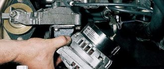
Good day everyone. The problem with the lack of an alarm signal has been solved. I’ll start with a photo of where its fuse is located - namely the alarm, but not the turn signals. The first thing you need to do is find and check it - the arrival of the “plus”, the integrity of the fuse and the output of the “plus” to alarm button. The problem is not standard, but it also happens. In the emergency alarm button, which is shown in the next photo, the button return spring was bent and did not allow it to be pressed fully and the contacts closed. I removed the entire control panel and left only the emergency light button itself.
Next, it was very convenient to carry out measurements. But in order to carry out at least some kind of measurement, you need to know the structure of the electrical apparatus. For this reason, the alarm button was disassembled. Next, the situation inside the apparatus was assessed with a “quick eye” and a mental schematic diagram of the operation was presented. I show the simplest one in the photograph a sketch diagram for measuring without disassembly and possible damage (in the absence of experience), the functionality of the alarm button.
What to do if the turn signals and emergency lights do not work? Looking for faults
Probably every driver has encountered a similar problem, but not everyone knows what to do if the turn signals and emergency lights do not work.
In particular, many questions may arise from new car mechanics who are not yet accustomed to repairing their car themselves. For example, in the morning when starting the car, inserting the key into the ignition, we check: but neither the turn signals nor the emergency button function as expected. What can be advised in this case, because, as a rule, inexperienced drivers begin to panic. Yes, indeed, without working turn signals indicating the direction (and even more so, coupled with emergency lights, which at worst could be turned on to indicate a breakdown and continue driving), it is not even recommended to leave the garage. This is fraught with an accident, especially if the traffic on the road is quite intense. So it's better not to take risks.
Why don't turn signals and emergency lights work, and what can I do about it?
Turning lights are an integral element of optics in any modern car. Their purpose is to warn other road users that the driver is planning to make a maneuver. For what reasons do turn signals and emergency lights not work, how to check the functionality of optical elements and how to repair them. We will talk about this below.
Content
In most cases, the whole issue is in the relay, which is responsible for this segment of the electrical system. Therefore, it is advisable to start checking with him. Water may get into the relay, or a contact may break off somewhere. You can fix it by replacing the spare part itself. It’s good if you have a spare one in stock for this case (some experienced VAZ owners always carry one with them).
If not, you will have to go to the nearest auto store, since it is not recommended to drive a car without direction indicators (or ask a friend with a car to go get the part). After replacing the relay, as a rule, everything starts to function.
Connection diagram
In fact, in order to understand the causes of a malfunction with turn signals and emergency lights, you need to know what the electrical diagram of their connection and connection looks like in a car. Because if manipulations with the relay do not help, then you will have to ring the entire circuit, and for this it is advisable to imagine what it consists of. Let's look at the example of the VAZ "classic" (although in the imported version it is unlikely to differ significantly).
The system has several main parts. Relay, usually on 4 wires. Emergency button. Turn switch. They are connected to each other by wires. In the normal position of the emergency button, the contact is closed from the ignition and goes (along the black wire) to the relay. There is now voltage on it, which is supplied to the turn switch. When turned left/right, the contact closes and the corresponding light comes on.
When the emergency button is turned on, the network is connected directly to the right/left turn lamps simultaneously. That's the whole scheme, if we tell it in a simplified way.
Emergency button and connector
Having studied the theory, we move on to practice. From the diagram above you can see that it all starts with the emergency button. It receives current from the ignition. Therefore, you should first check whether voltage is being supplied to the connector. Perhaps the contact wire has come loose, or perhaps, by the way, the fuse has blown (look in the instruction manual to see which one is responsible for this section, and try to replace it with a spare one).
You can use a multimeter to check the input readings: the orange wire supplies power from the lock. In black - it goes to the relay. There is also a red one - the on-board network, there should always be voltage there (after all, the emergency lights can work even when the ignition is turned off).
Let's check the insertion of the corresponding wires into the connector; perhaps something has come loose or frayed. If you don't have electrical meters on hand, you can use a small piece of wire to check the integrity of the wiring diagram.
To do this, disconnect the hazard warning button itself from its connector. We get a socket with several outputs, hanging on wires of different colors. Using a piece of wire inserted into the corresponding connectors (jumpers), you can simulate the operation of both the power button itself and the turn signals in order to understand that the corresponding sockets are working.
Continue checking
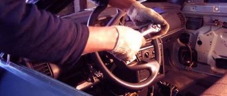
Next, what to do if the turn signals and emergency lights do not work? If the relay with the connector and button is exactly the same (as we were convinced of during the checks), you can look for other causes of problems. For example, pay attention to the turn switch on the steering wheel. It happens that there is no voltage contact there. The test is carried out without the participation of a switch on the relay connectors: using a piece of wire you can close the corresponding contacts.
If the turn signals work, then it means that this particular steering switch is faulty (no current is supplied to it for some reason). Here, without proper preparation, it will be quite difficult to replace or repair the part yourself, since you will have to remove the steering wheel and the switch itself. In this case, it is better to contact the services of an electrician at a service station.
Emergency signal malfunctions
If the VAZ 2114 emergency light does not work, then troubleshooting should begin with the fuse box. To do this, you need to check and, if necessary, replace with a new one, 10 Amp fuse F2. Simultaneously with checking the fuse, you should inspect and clean the contacts in the mounting socket of the common unit (if they are oxidized, the emergency light may not work even with a working fuse).
The next step in finding a breakdown is to check the presence of voltage at contact X2/5, which is located on the mounting block (this is done using a multimeter and with the emergency button turned on).