The ignition switch in cars of the VAZ family fails from time to time due to weakening of the contact posts or burning of the contacts inside it. It also happens that the cams of a plastic roller are produced. You can disassemble the lock and clean it, but it’s better to just replace it with a new one, considering that it costs pennies compared to imported locks.
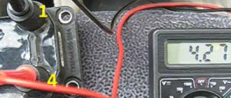
But if connecting the wires together did not result in the starter operating (or it did not turn on the first time), check the solenoid relay on the starter. The contact spots on it may also burn out, which will prevent the circuit from closing normally. Alternatively, you can use a screwdriver to short-circuit the two large terminals on the solenoid relay (before doing this, put the car in neutral and use the handbrake). When closed, the starter should begin to spin vigorously. If this happens, remove and change the solenoid relay. If the starter rotates “sluggishly” when it closes, you will have to remove it and check the condition of the brushes.
All operations are performed with your own hands, without the help of car service specialists. Moreover, the price of an ignition switch on a VAZ2106 is up to 100 rubles. To replace it, you will need to know the pinout of the wires coming from it, for which the editors of the site 2 Schemes.ru have prepared a large reference material.
The ignition switch is designed not only to start the engine - it performs several functions at once:
- supplies voltage to the vehicle’s on-board network, closing the circuits of the ignition system, lighting, sound alarm, additional devices and instruments;
- at the driver’s command, turns on the starter to start the power plant and turns it off;
- turns off the power to the on-board circuit, preserving the battery charge;
- protects the car from theft by fixing the steering shaft.
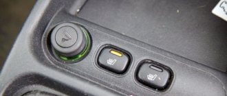
This option is for those who want to illuminate the BSK block without plexiglass
We erase the front plate with a stationery knife.
Print out the same drawing again, but on matte paper.
It goes something like this
Then I made holes in the case with a soldering iron.
To diffuse the light, I inserted pieces of transparent plastic into these holes (cut from a simple CD box) and made one side matte with a knife, but better with sandpaper
Now we are illuminating the Vase, which I forgot to photograph.
To illuminate the BSK module, I took a diode strip (2 pieces from it)
There are no pictures, so I took approximately the same module as a base and added LED strips there. I think the meaning is clear.
The strips need to be glued between the door LEDs
I soldered the backlight wires to pins 1(+) and 3(-) to these
Now the drawn car on the block will glow brightly when the ignition is on.
In order for the car to not glow so brightly, I soldered a 620 Ohm resistor to the positive wire.
Errors when connecting/operating the on-board computer
Error: “No connection with the controller” or “break in the K-line.”
It indicates that the K-line is not connected or a contact break has occurred. Check the wire according to the diagram described above. Most likely, the contact has come off the diagnostic block.
Error: Incorrect temperature sensor readings.
If, according to the instrument readings, your temperature outside is -40, then this indicates that a wire has broken or there is no such analyzer at all. If the sensor shows -25, but it's only -10 outside, then you need to replace it.
Peculiarities
VAZ 2114 cars have many innovations compared to 2109, in particular, this concerns electrical wiring.
Whether it is an injector or a carburetor, the wiring diagram for the VAZ 2114 is located in:
- vehicle interior;
- in the engine compartment;
- behind the car body.
It should be noted that carburetor VAZ 2114 were produced only from 1997 to 2000, then they were equipped with carburetors from the VAZ 2108.
But new engines have a more powerful ignition system; accordingly, the electrical control circuit is also characterized by certain features, for example:
- There is a new harness for connecting to the ignition module terminal. This component sends signals to the spark plugs through high-voltage wires.
- Another harness was added to allow mounting of the switch.
- Additional wiring has appeared to connect the adsorber valve to the injection system controller.
Wiring and equipment diagram 2114
Many VAZ 2114 car owners mistakenly believe that thanks to the ignition module, they don’t have to use a coil. In fact, this device is equipped with two coils and two switches. One of the coils transmits the signal to the first and fourth cylinders, and the second - to the second and third.
The equipment system of VAZ 2114 cars with an injector engine has undergone certain innovations not only due to the addition of new electrical equipment, but also as a result of modernization of the car as a whole:
- it is possible to install a heated side mirror device;
- you can connect the front seat heating system;
- VAZ 2114 car owners can install PTF, etc.
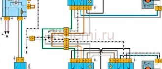
Ignition and engine control circuit
Here are the control diagrams for the following internal combustion engines:
- 21120 – January 5.1 or BOSCH M1.5.4N, Euro-2;
| Motor | 21120 (Euro-2) | 21124 (Euro-2) | 21124 (Euro-3) |
| Injectors | 1 | 2 | 2 |
| Ignition coil | — | 1 | 1 |
| Candles | 2 | — | — |
| Ignition module | 3 | — | — |
| Diagnostic connector | 4 | B | B |
| ECU | 5 | 3 | 3 |
| Tidy taps | 6 | E | E |
| Ignition relay (6) | 7 | 4 | 4 |
| Ignition fuse (1) | 8 | 5 | 5 |
| Fan relay (4) | 9 | 6 | 6 |
| Fan fuse (2) | 10 | 7 | 7 |
| Fuel pump relay (5) | 11 | 8 | 8 |
| Fuel pump fuse (3) | 12 | 9 | 9 |
| Mass air flow sensor | 13 | 10 | 10 |
| Rough road sensor | — | — | 11 |
| TPDZ | 14 | 11 | 12 |
| DTOZH | 15 | 12 | 13 |
| RXX | 16 | 17 | 14 |
| Lambda probe main | 17 | 14 | 15 |
| Additional lambda probe | — | — | 16 |
| Knock sensor | 18 | 15 | 18 |
| DPKV | 19 | 16 | 19 |
| Canister purge valve | 20 | 13 | 17 |
| APS block | 21 | 18 | 20 |
| APS indicator | 22 | 19 | 21 |
| Speed sensor | 23 | 21 | 23 |
| Fuel pump + level sensor | 24 | 22 | 24 |
| Oil pressure sensor | 25 | 23 | 25 |
| Antifreeze thermometer sensor | 26 | 24 | 26 |
| Oil level sensor | 27 | — | — |
| Phase sensor | 28 | 20 | 22 |
| ABS connector | A | A | A |
| Air conditioner connector | B | IN | IN |
| Fan connector | C | — | — |
| Illumination of the ignition switch (to the blue-white wire) | D+E | — | — |
| Bends to the door harness | — | D | D |
| + battery | F | G | G |
| Weight | G1+G2 | G1+G2 | G1+G2 |
The elements installed in the additional mounting block are indicated in brackets.
Mounting block on the right side under the dashboard
Standard connection tw 9010
The Tomahawk equipment manufacturer suggests connecting the alarm as follows:
Reviews tell us that the standard connection option in VAZ cars is easy to implement. You don’t have to connect the hood switch, the Anti-Hijack button, and the “blue-red” wire coming from the connector is definitely not needed. You can connect a blocking relay connected to the “black-yellow” cable if autostart is needed. In general, connecting the Tomahawk tw 9010 signaling system is a pleasure if we are talking about a VAZ-2110.
There are two connectors under the dashboard of the VAZ 10s. They are painted white and red. When making T-shaped connections, the following wires are pulled from the connectors:
- Tachometer cord connected to pin “3” of the white connector;
- Parking brake sensor wire (white connector);
- Two cords from the turn signal lamps (terminals 5 and 6 of the red connector).
All Tomahawk car alarm systems allow the starter to be disabled. If the owner needs this option, then a relay is connected to the break in the “50P” cord.
Blocking using an “external relay” is a standard option for the Tomahawk tw 9010 alarm, unlike the tz 9030 systems.
If you do not need interlocking, still connect the “yellow” cord of the 6-pin connector to the “15GCH” terminal.
Information indicators of the VAZ 2110 instrument panel
All information indicators of the VAZ 2110 car system are indicated by arrows, here they are in the photo:
Information indicators of the VAZ 2110 dashboard
- Availability and temperature of coolant
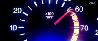
- Tachometer (shows the number of engine revolutions, remember to multiply by 100)
- Speedometer (shows the speed of the car. There is no need to multiply anything here.
- This display shows the vehicle's total/daily mileage.
- Engine oil indicator.
As you can see, the instrument panel of the VAZ 2110 is not that difficult to study. But very often situations arise when errors appear on the dashboard. Let's now look at these errors in more detail.
Car radio connection options
The main elements, in addition to the device itself, are the connectors. They are:
- The international standard is ISO connectors.
Advice: ISO standard plugs must not be used for purposes other than their intended purpose. This may lead to equipment failure.
- Individual. In this case, you can buy an adapter for the ISO connector or cut the wires from the radio plugs and the car wiring, then connect the car radio according to the color wiring of the device. You can use electrical tape for winding. But besides the fact that this method of installing a car radio is not aesthetically pleasing, it is not always reliable. The connection of the wires does not guarantee a tight fit and sticking of electrical tape on the wires, especially in winter, which can lead to a short circuit.
Advice: This method can be done, as a last resort, taking precautions and using heat-shrinkable tubes.
It is enough to install ISO standard connectors once and you no longer need to think about how to connect a pioneer car radio. You will need to pull out the old device along the slide and switch the plugs from the old product to the new one, which is then put in place. The photo shows ISO standard plugs.
ISO plugs
ISO standards for connecting car radios
There are some features and different colors of plugs that you need to use to properly connect your pioneer car radio. There are two plugs as standard:
- Black. Through it, the device is powered and its additional functions are provided.
- Brown. Provides output to the car's acoustics for a sound signal.
When connecting the radio, the positive wire must be connected correctly.
Tip: When connecting the device, it is better to take the positive wire through the fuse directly from the battery. The diameter of the wiring should not be less than the diameter at the car radio connector. Sometimes you can connect from the cigarette lighter.
To reduce leakage, the following connection diagram for a pioneer car radio can be used:
Car radio connection diagram to reduce leakage
- Black color is earth.
- Yellow – power supply from the battery (+12 volts).
- Red – signal from the ignition switch to turn on the radio (+12 volts).
- Blue – antenna is turned on (+12 volts when the device is turned on).
- Diodes are different, maybe low-current type KD522B.
After installing the pioneer car radio, it is connected by applying a plus to two wires: yellow and red:
- The yellow wire carries out settings and is responsible for powering the product’s memory.
- Red is power and turns off the radio.
The instructions indicate that the red wire should be connected through the ignition switch, which will ensure that the device turns off after the ignition is turned off.
Ignition switch malfunctions
The ignition switch on a VAZ 2110 must be replaced if its operation cannot be restored in any way or the key is broken/lost. In other cases, they are usually repaired.
There are two groups of main breakdowns:
- The mechanics are faulty . The most common problem is the breakage of the larva. The keys are made of soft metal, so they are unreliable and can often simply break off. There is also a problem with the steering wheel locking or the key may simply get stuck when in the on position.
- Wear of the contact group . No matter what kind of damage you have, you will still have to dismantle the lock. If the tongue of the blocker is jammed, you will have to work hard to correct the situation. The contact group or larva is quite easy to repair.
In order to check the ignition switch on a VAZ 2110, there are many instructions and methods, we will consider some of them.
Detailed instructions for checking faults in the ignition switch:
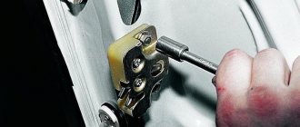
- The first thing to do is disconnect the wire from the negative terminal of the battery.
- Remove the plastic cover of the steering column to get to the contacts of the pads, because it is with their help that power is connected to the car's electrical wiring. Next, disconnect the connector of the harness itself from the on-board network and pull it out.
Description of indicators and lamps on the instrument panel of the VAZ 2110
Well, we laughed, now let's move on to the main thing: a description of the indicators and lamps on the instrument panel of the VAZ 2110.
Description of instrument panel indicators BA3 2110
- Oil in fuel indicator
- Handbrake indicator
- Automatic battery charging indicator
- Engine health indicator
- Additional engine health indicator
- Enable left turn
- Enable right turn
- High beam indicator
- Brake fluid level indicator
- Fuel indicator
- Indicator of the warning lamp for turning on the dimensions
All of the indicators described above (except for the turn indicators and high beam headlights) are warning in nature. If they light up, then there is a problem in the car system.