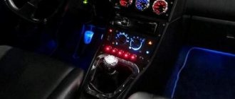
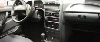
Let's be honest - the VAZ 2110 does not have the most beautiful “native” instrument panel, either on the first cars or on the “improved” ones. Therefore, many owners of this model are trying to make it more modern and somehow decorate it (with LEDs, beautiful lights, etc.).
But, before you decide on some kind of upgrade, it is necessary that you have before your eyes the pinout of the instrument panel for the VAZ 2110, otherwise you can simply get lost in a heap of wires, sensors and buttons. Moreover, it will be useful regardless of whether you completely change the panel, or simply make some additions to the dashboard of your VAZ 2110.
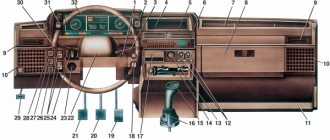
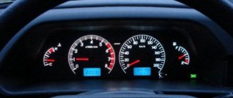
Instrument panel VAZ 2110
Connection knowledge
Before starting dismantling work, you need at least a conventional pinout on paper, otherwise it will be very difficult: you will need to “trace” every wire and every connection that is on the “path” from the devices to the power button.
In fact, the pinout of the VAZ 2110 dashboard is not so difficult to understand, but there are differences between cars produced in different years and at different factories. There is an old model, there is one with a mechanical odometer, and a new (Euro) model, so there are differences in the pinout of the instrument panel, depending on the type to which it belongs.
Instructions for installing the Europanel on a VAZ 2110 can be found here:
General diagram of devices
If you look from the back of the instrument panel, here it is in sequence - from top to left to right:
- Fuel level indicator;
- Combination of instrument lighting lamps;
- Right turn control;
- Left turn control;
- Tachometer;
- Next is the block, there are a lot of plugs in it;
- And the top part of the dashboard is completed by an antifreeze temperature indicator.
VAZ 2110 dashboard connection diagram
The lower part of the dashboard (also from left to right and from the back of the dashboard). The following part of the instruments is located here:
- high beam controller (bulb);
- alarm controller;
- brake fluid level control lamp;
- speedometer;
- CHECK ENGINE controller;
- battery charge control;
- parking brake controller;
- oil pressure controller;
- air damper controller in the carburetor;
- outdoor lighting controller.
You can familiarize yourself with speedometer malfunctions in this material:
White block
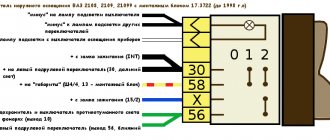
The connector number, wire color and the unit (assembly) to which it goes are located in the white block as follows:
- The first connector has a black wire. Its purpose is the body (mass);
- In the second - red-brown - this is a low-voltage supply from the electronic control unit - tachometer;
- The third, yellow one is also a tachometer, but this is a high-voltage supply from a coil;
- The fourth, red-blue is Const from the battery + 12V, going through the sixth fuse;
- The fifth, green-white - it is intended to indicate the coolant temperature;
- Sixth, green-yellow – for size fuse F1;
- The seventh connector does not have its own color and goes to the “choke”, the throttle valve;
- Eighth, red and white - CHECK ENGINE light;
- In the ninth and tenth there are 2 orange wires each, leading to 2 power fuses F19+12V;
- In the eleventh there are 2 blue-brown wires leading to the “BK” terminal of the parking brake;
- The twelfth, brown-white is the output “D” of the generator;
- Thirteenth, gray and blue – for the oil pressure sensor.
White block (X1) and Red block (X2) of the VAZ 2110 instrument panel
Red block
The number is the connector according to the account, followed by the color of the wire and an indication of the device to which it goes in the red block of the VAZ 2110:
- Blue and red go to the sensor showing the external temperature;
- Orange - power fuse F19+12V;
- Black, 2 wires – ground, body;
- White - light switch for all devices;
- Blue - right direction indicator;
- Blue and black - left turn signal;
- Blue with pink - TJ level;
- Brown – leading to the trip computer;
- Gray - speed indicator;
- Pink - Fuel gauge (terminal “T”);
- 2 black-green wires - high beam fuse (F3);
- Blue and white - emergency light switch;
- White - leading to the ignition switch (terminal 50).
An article dedicated to tuning the dashboard backlight can be found here:
Malfunctions and repairs
Instruments or indicators may fail. This could be part of the indicators or even the entire speedometer. VAZ 2110 owners rarely encounter this situation, since the dashboard works properly, especially in domestic cars. Before changing the instrument panel or repairing individual parts, you should make sure that the sensors are working properly - we use the on-board computer.
Inaccurate installation leads to failure of elements. On the instrument panel board, the parts are attached using simple rivets, hence the negative result. The body is constantly subject to vibrations, so the installation simply “falls apart” and breaks appear in the circuit. Repair in this case involves soldering the rivets and thoroughly cleaning the contacts.
- It is necessary to remove the plug; the board does not need to be disconnected from the case.
- The next step is to apply flux to the places on the board with arrows (photo below). Both pads also need to be removed and thoroughly lubricated.
After soldering is completed, the instrument panel can be returned to its place. If you have free time, you can go through the contacts using sandpaper. On older cars they usually oxidize, which can prevent the devices from functioning properly.
You can see how to remove the dashboard in the video below.
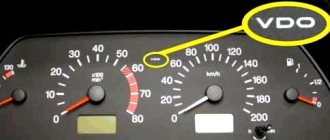
Glowing VDO instrument panel from VAZ 2110
I missed the Latvian illuminated instrument cluster (CI) - I didn’t buy it in the summer of 1999, when it cost 600 rubles. And now the situation with them is quite tense, or more precisely, “... there is no delivery and is not expected.” They say that they are in Tolyatti, but for $80 with a speed sensor. Expensive…
However, in markets and stores there is an abundance of VDO instrument clusters for the VAZ 2110 car, model 2110-3801010-02, which is also installed on the 115 VAZ model. In relation to the “eighth” panel, it has disadvantages:
- Doesn’t fit very well; you’ll have to cut the torpedo visor, otherwise some of the lamps will not be completely visible;
- There is no built-in BSK (on-board control system);
- It is necessary to select a fuel level sensor with the appropriate resistance, otherwise the indicator may be “slightly misaligned”.
Otherwise there are only advantages
- All instruments are more accurate, especially noticeable in the fuel level and coolant temperature sensors;
- The speedometer and tachometer are located in the center, all arrows are controlled by stepper motors - the movement of the arrows is smooth;
- The fuel light doesn't blink like crazy, because... it is ignited by electronics, and not by a contact in the tank;
- The total and daily mileage are displayed on the LCD display - when the car is not started, the mileage is not visible on the instrument panel. Relevant for new cars.
- There is a self-diagnosis mode - you need to turn on the ignition while pressing the reset button for the daily mileage counter.
Another plus: the speedometer cable becomes unnecessary, which often makes various sounds - sometimes it clicks, sometimes it clicks... True, I also had to buy a DS (speed sensor, since I have a carburetor car). The sensor needs to be taken only with an iron pin and a connector identical to the connector of the Hall sensor - it is easier and much cheaper to buy a chip for it.
Connection
Three chips fit the standard CP: white (X1) and red (X2), also one smaller red one (for BSK). Before changing the wires, a bundle of wires from the red block was pulled through the window in the dashboard next to the wires of the white block. Otherwise, you won’t be able to remove the dashboard later—tangled wires won’t allow it.
Nuances of work
However, these pinout diagrams for the VAZ 2110 are, so to speak, basic, mostly the same, but there are also differences in color markings (especially by manufacturer). Therefore, you need to either use the instruction manual that came specifically with your car, or, armed with a marker and self-adhesive labels, “write everything out” in detail and not get confused when installing a new instrument panel.
Connecting wires to the VDO panel on a VAZ 2110
Connecting wires to the “Schetmash” panel in Kursk on a VAZ 2110
Connecting wires to the “AP” panel in Vladimir on a VAZ 2110
Connecting wires to the panel from the Kalina car to the VAZ 2110
During subsequent assembly, there will probably be a lot of devices that are not taken into account here, and, taking into account modern realities, many car owners plan to install them on the updated dashboard.
Pinout
If you want to perform repairs or other operations on the instrument panel, then you need a VAZ 2110 pinout. If you don’t have it, you will have to track every wire from the indicator, button to the device. The diagram allows you to determine which of the devices does not work in the event of a malfunction in one or another node. If the indicators in the old and new VAZ 2110 are identical, then the pinout is slightly different. There are two pads - red and white. Pinout may seem complicated only at the beginning. Let's take several connectors as an example.
The first number indicates the black wire that goes to ground. The thirteenth number is tied to the oil pressure sensor in the system, as the diagram tells us. The white block indicates the connector number, the wire and the unit (unit) to which the wiring goes. The red block is read in exactly the same way. The first connector contains blue and red wires; they go to the external temperature sensor. As for number thirteen, here the white wire leads to the ignition switch.
see also
The pinout and diagram shown in this article are basic. They may differ in color marking, because many variations of the VAZ 2110 have entered the market. To avoid confusion, it is recommended to compare the data from the article with the instruction manual, which also contains a diagram and pinout.
Connecting the trip computer
The mentioned diagram took into account only one, brown wire leading from the red block to the trip computer, but this is clearly not enough. Therefore, let's see how the pinout occurs here.
- The fuel consumption signal from the electronic control unit is indicated by a green wire;
- Orange leads to terminal “15” in the ignition switch;
- Red and white - to terminal “30” in the ignition switch;
- Black, which is common, goes to ground;
- The speed indicator corresponds to brown;
- The positive terminal of the fuel sensor is green and red;
- Responsible for lighting the dashboard white, it leads to the light control.
Make sure that the board is not damaged, on which, in fact, uninterrupted reading of information from your VAZ 2110 depends, and providing it to you through all those sensors and devices that you always see in front of you.
- Author: ratico19
Rate this article:
- 5
- 4
- 3
- 2
- 1
(14 votes, average: 3.4 out of 5)
Share with your friends!
Pinout of the dashboard VAZ2108, 2109, 21099
Connection diagram of the instrument cluster before 1996.
1 — relay-interrupter for the parking brake warning lamp; 2 — tachometer with voltage stabilizer; 3 — instrument cluster lighting lamp; 4 — temperature indicator; 5 — BSK control unit; 6 — fuel level indicator; 7 - resistor 50 Ohm, 5 W; 8 — “CHECK ENGINE” control lamp for the toxicity reduction system; 9 — control lamp for high beam headlights; 10 — side light indicator lamp; 11 — backup warning lamp; 12 - warning lamp for unfastened seat belts; 13 — control lamp for left direction indicators; 14 - resistor 470 Ohm, 0.25 W; 15 - electronic voltmeter; 16 — control lamp for right direction indicators; 17 — warning lamp for emergency oil pressure; 18 — fuel reserve warning lamp; 19 — control lamp for the carburetor air damper; 20 — “CHECK ENGINE” warning lamp for the fuel injection system; 21 - parking brake warning lamp.
Instrument cluster wiring diagram after 1996
1 — tachometer; 2 — instrument cluster lighting lamp; 3 — temperature indicator; 4 — BSK control unit; 5 — fuel level indicator; 6 — “CHECK ENGINE” warning lamp for the toxicity reduction system; 7 — control lamp for high beam headlights; 8 — side light indicator lamp; 9 — backup warning lamp; 10 - warning lamp for unfastened seat belts; 11 — control lamp for left direction indicators; 12 — battery charge indicator lamp; 13 — control lamp for right direction indicators; 14 — warning lamp for emergency oil pressure; 15 — fuel reserve warning lamp; 16 — control lamp for the carburetor air damper; 17 — “CHECK ENGINE” warning lamp for the fuel injection system; 18 — parking brake warning lamp; B1 - 91 kOhm resistor; B2 - resistor 50 Ohm, 5 W.