Payment for goods and downloading of the book in electronic form (PDF format) is made on the website.
To do this, you need to find the book you are interested in and click on the “Buy” button. The price of the book is indicated on the button.
For convenience, the price on the website for residents of Russia, Belarus and Kazakhstan is presented in rubles.
For residents of Ukraine in hryvnias, and for all other countries - dollars.
After clicking on the “BUY” button, a payment window will open where you can select a payment system with which you can pay for the selected book using any bank card (Visa, MasterCard, MIR, etc.)
When you click on the “Pay by bank card” button, the Portmone payment system will open, which is the easiest way to make a payment.
In addition, the website offers four payment systems for payment:
- Yandex (payment from any bank cards, Yandex Money account, QIWI Wallet, terminals, etc.);
- Portmone (payment from any bank cards, Portmone account);
- PayPal (payment from any bank cards, PayPal account);
- WebMoney (payment from any bank cards, payment from WebMoney wallets).
Payment via Yandex Cashier
After selecting payment via Yandex, the Yandex Cashier payment system will launch, where you need to select a convenient payment method (bank card, QIWI, Yandex Money account, etc.)
After specifying payment details and confirming payment, payment for the goods will occur.
If you have a bank card in a currency other than the ruble, then the money will be debited from the card at the rate of the Central Bank of Russia at the time of the purchase.
This payment method is optimal for residents of Russia, Kazakhstan and Belarus.
Official website of the Yandex Kassa payment system https://kassa.yandex.ru
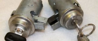
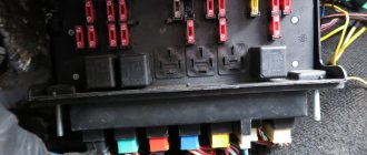
How are the main wiring elements of the VAZ-2106 car protected?
The electrical wiring of the machine is protected by fuses, which are mainly installed in the central and additional units, located at the bottom of the instrument panel on the left side next to the steering column. The circuit from the battery to the terminals and connections is closed when the car ignition is turned on.
Tip: when carrying out work to replace or repair lighting fixtures and wiring, be sure to disconnect the battery from the network. Relays, switches, batteries, spark plugs, and even the relay winding in the lighting system and fan in the cooling system are not protected by fuses. When bleeding the brakes on a VAZ-2107, a similar problem may arise.
If one of the circuit elements is damaged, the fuse trips. If a malfunction occurs in the main set of fuses, the backup fuses are switched on, which are additionally installed next to the ignition unit. If a blown fuse is detected, it is not enough to just replace it - you need to study the wiring in detail and find out the reason for the combustion of this spare part in the VAZ-2106.
The electrical equipment and wiring diagram should help you quickly find and eliminate faults in the headlights, dashboard indicators and other systems of your VAZ-2106.
Payment via Portmone
After selecting payment through Portmone, the payment system will launch, where you need to select the payment method: bank card or Portmone account.
The price in the Portmone payment system is converted into dollars at the exchange rate of the Central Bank of the country where you are located.
If you have a bank card in a currency other than the dollar, then the money will be debited from the card at the rate of the Central Bank of your country at the time of the purchase.
After specifying payment details and confirming payment, payment for the goods will occur.
Official website of the Portmone payment system https://www.portmone.com
The central part of the electrical equipment diagram of the VAZ-2106
The central piece of the circuit mainly consists of light on/off switches and switches for supplying current to the system.
The main wiring elements are indicated by the following numbers:
- Kit with main fuse block (30);
- Light switches in the car's reversing headlights (31), operation of warning lamps when the hand brake is applied (32);
- Types of plug sockets for portable lamps (33);
- Equipment for operating the turn signal and hazard signal (34);
- Design of the electric motor of the stove (35) and the terminal for turning off the brake light (36);
- Current supply relay for heating the rear window (37);
Tip: depending on the modification and year of manufacture of the VAZ-2106, the type of relay and its position in the network may change. To repair this spare part, it is best to use the diagrams that come with the machine.
- Set of resistors for the VAZ 2106 heater electric motor (38);
- Wiring to the light bulb in the glove box (39);
- List of switches for exterior lights (40), heating the rear surface of the glass (41), as well as the ignition system (42);
- A set of switches from low to high beam (43), a windshield wiper (46) and a car turn indicator arrow (44);
- Special types of vehicle horn switches (45), universal windshield washer switches (47) and dashboard light and emergency signal controls.
Payment via PayPal
After selecting payment via PayPal, the PayPal payment system will launch, where you need to select the payment method: bank card or PayPal account.
If you already have a PayPal account, then you need to log into it and make a payment.
If you do not have a PayPal account and you want to pay using a bank card via PayPal, you need to click on the “Create an Account” button - shown with an arrow in the picture.
PayPal will then prompt you to select your country and provide your credit card information.
After specifying the information required to make the payment, you must click on the “Pay Now” button.
Official website of the PayPal payment system https://www.paypal.com
Instructions for dismantling the instrument scale
Removing the casing requires work with a 10 mm wrench and several screwdrivers. The panel is dismantled if it needs to be replaced, as well as when performing body work, since it can become an obstacle and become damaged. The actions are performed in the following order.
- In the glove compartment, unscrew several nuts on the outermost fastening of the instrument panel and the bolts located under the instrument cluster.
- Carefully, using a screwdriver, remove the plate from the receiver casing with auxiliary adjustment units, inside which there are several bolts securing the radio panel. It is advisable to remove them, while supporting the mounting bar and preventing it from falling. Remove the receiver panel.
- Move the fastening nuts and remove the decorative elements of the steering column.
- Taking care not to damage anything, use a screwdriver to move the clock in the panel. It is advisable to mark and disassemble the wiring, remove the backlight from the clock and remove it.
- Separate the wire from the light box illumination lamp.
- Unscrew the mounting bolts and remove the work shelf.
- Remove the fastening bolts at the bottom of the panel.
- Remove the switch for the electric interior heating fan, mark the connection points with a marker and remove the switch. Using a screwdriver, remove the handles of the heating shutters.
- Remove the instrument panel. Using a screwdriver, lift it up at the fixing points and pull it forward. Unhook the cable from the speedometer. Be sure to mark the packages of electrical wires so as not to get confused during installation. Unplug the electrical wiring and remove the instrument panel.
- Remove both side decorative trims from the windshield frame by removing the three fastening screws.
- Release the radio panel by removing the side fasteners.
- Lift and remove the panel from the VAZ 2106.
This completes the dismantling of the VAZ 2106 instrument panel. Assembly is carried out in reverse order.
Payment via WebMoney
After selecting payment via WebMoney, the payment system will launch, where you need to select the payment method: bank card or WebMoney wallet.
If you already have a WebMoney wallet, then you need to log into it and make a payment.
If you do not have a WebMoney wallet and you want to pay in another way, you need to select any of the methods that WebMoney offers and make the payment
After specifying payment details and confirming payment, payment for the goods will occur.
Official website of the WebMoney payment system https://www.webmoney.ru/
So, everything seems to have been pulled together, now let’s get to work:
We remove the standard tidy along with the steering wheel. Removing the instrument panel 2101 is described in detail in the manual for 2101. The steering wheel can not be removed, but then the inconvenience during operation greatly increases.
We try on the dashboard to the seats on the body. The differences in the 2101 and –06 devices immediately become visible:
We begin to eliminate the listed interference:
Installation of both stove levers and places for mismatched fastening (Fig. 6)
The heater valve cable is short. Looking carefully at the end of the cable that fits onto the heater valve lever, we see that it is twisted into a ring 3 times - this is the necessary reserve. Unwind the ring - leaving 1 turn (Figure 
The cables are sorted out. Now let's figure out where to place the offset fasteners!
We make a U-shaped bracket (Fig. 9)
Figure 9 – bracket for fastening
And we weld it to the intended place for fastening the dashboard -06. The result is a picture - Fig. 10
Figure 10 – Displacement of the fastening point
Now let's take care of the suction - we need to make brackets for it and place it approximately in the place of the old suction. The bracket is made according to TheForester's drawing (special thanks!)
Figure 11 – Homemade suction bracket
Figure 12 – Hand-made bracket for suction
We weld this example of crazy hands to the crossbar:
Figure 13 – Welded to the cross member
After welding, do not forget to prime to avoid rusting.
We insert a cable with suction into the manufactured bracket and screw in the end switch.
There is another important point - because. the speedometer in 2106 is shifted to the right than in 2101, then it is necessary to rewind the sidometer cable differently (see Fig. 14), however, due to the fact that the cable 2101 is longer, in the new place its length turns out to be excessive even after installing the panel due to excess radii If the cable bends, the speedometer needle may shake, so I recommend using a cable from 2103, 2106 that has a shorter length.
Figure 14 – location of the speedometer cable
This is where the mechanical part of the installation actually ends and the electrical part begins:
We screw the oil pressure indicator sensor with a tee (Fig. 4) and tighten the wire from the sensor into the passenger compartment, do not forget to put on the boot (2101-3724114 Fig. 4). We tighten the wire from terminal K - the ignition coil into the passenger compartment. We make a connection with the instrument panel harness 2106. The connection diagram when connecting new devices can differ greatly from model to model due to differences in the colors of the on-board network wires, and even the instrument panel harness 2106, so the correct one will be look at your diagram in place and make the appropriate connections.
In short, the decision comes down to a banal reconnection of wires. In 2101 there are 2 connectors of 6 contacts on the left and right, in 2106 - the left connector has 8 contacts, and the right one also has 6, like 2101.
Downloading a book
After successfully completing the payment (by any method) and returning to the KrutilVertel store from the payment system website, you will be taken to the successful payment page:
On this page you need to indicate your e-mail, where access to download the book will be sent.
If you are already registered on our website, then simply follow the link to your personal account.
The book you purchased will be in your personal account, from where you can always download it.
Please note that after making the payment, you need to return back from the payment system website to the KrutilVertel website.
If for some reason you did not return back to the site and closed the payment system tab with a message about the successful completion of the payment, please let us know - we will send you a letter indicating access to download the book.
Upper left part of the VAZ-2106 wiring diagram
This diagram allows you to examine the elements of the front of the machine. Here are the following:
- Side left and right turn signal (1);
- Several sidelights (2);
- External (3) and internal (4) headlight samples;
- Connected sound signal (5).
Next are the internal elements of the car's electrical wiring, which are hidden under the hood and body. These include:
- Electric motor terminals for both fans included in the cooling system of the VAZ-2106 engine (6);
- A set of sensors responsible for the timely activation of the electric motor (7);
- 2 types of relays - one is used when turning on the sound signal (8), and the other when regulating the operation of the electric motor of the cooling system (9);
- Small voltage regulator in the car (10);
- Vehicle ignition system coils (11);
- 2nd electric motor, which is responsible for the operation of the windshield washer (12);
- One of the main sensors of the VAZ-2106 - it determines the level of brake fluid in the car and promptly gives the owner a command about non-compliance with the required standards (13);
- Also marked in the center of the diagram are the ignition system distributor (14) and the motor for operating the windshield wiper (15).
This part of the circuit is completed by the following electrical equipment:
- Car spark plug set (16);
- Sensors monitoring the oil mixture pressure lamp (17) and a gearbox with an indicator of this pressure on the panel (18);
- Also shown is the connection of the sensor for the current temperature indicator in the engine coolant (19) and the engine compartment lamp of the VAZ-2106 (10).
Advice: if problems arise with the operation of the engine and specifically the chassis, first check the tire pressure in the car using the table - are all the wheels properly inflated? Then start researching your wiring problems!
Problems when paying with bank cards
Sometimes difficulties may arise when paying with Visa/MasterCard bank cards. The most common of them:
- There is a restriction on the card for paying for online purchases
- A plastic card is not intended for making payments online.
- The plastic card is not activated for making payments online.
- There are not enough funds on the plastic card.
In order to solve these problems, you need to call or write to the technical support of the bank where you are served. Bank specialists will help you resolve them and make payments.
That's basically it. The entire process of paying for a book in PDF format on car repair on our website takes 1-2 minutes.
If you still have any questions, you can ask them using the feedback form, or write us an email at [email protected]
Schemes of individual six units
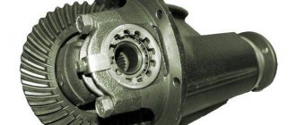
Generator connection diagram
1 — battery VAZ-2106; 2 — “six” generator set; 3 - regulatory device designed to control the operating voltage parameter; 4 - lock; 5 — plastic module with safety elements; 6 - control light indicator that determines the battery charge; 7 - relay that protects the power line of the battery charge indicator light.
Starter wiring diagram
1 — car starter device; 2 - battery; 3 - generator set; 4 - ignition switch.
Electrical circuits of the contact ignition system
1 — spark plugs; 2 - distributor; 3 — ignition switch; 4 - coil; 5 - switch; 6 - generator; 7 - battery.
Carburetor valve control circuit
1 - limit switching device of the carburetor unit; 2 - the engine valve itself; 3 - module used to control the carburetor unit; 4 — ignition coil; 5 - switching device; 6 - ignition switch, is a lock.
Wiring diagram of direction indicators and signaling
1 — lighting devices for turning lights installed in the front optical devices; 2 — battery VAZ-2106; 3 - car generator unit; 4 — side turning lights located on the front fenders; 5 — main mounting module with safety elements; 6 - auxiliary control unit with safety devices; 7 — ignition switch; 8 - device for turning off and activating the light signal, mounted in the car interior on the center console; 9 - switching device for activating and disabling turning lights; 10 - interrupting device used for blinking turning lights and light signals; 11 — speedometer, equipped with a control light indicator for activation of turning lights; 12 — light devices for direction indicators in the rear optics.
Electrical circuit for turning on the sound
1 - sound devices used to reproduce impulses; 2 - relay for activation of sound impulses, protects the electrical circuit from overvoltage; 3 — switch of sound pulses; 4 — mounting module with safety elements; 5 — generator set VAZ 2106; 6 - battery.
Switching diagram for electric windows
1 - main safety module; 2 - relay used to protect the power line of additionally installed power windows; 3 — switching device for the electric window mounted on the left door; 4 - a similar device used to adjust the position of the glass in the front right door; 5 — electric motor of the left glass lift; 6 — auxiliary module with safety elements; 7 - ignition switch.
Engine cooling system diagram
1 — generator unit, installed under the hood; 2 - battery; 3 - ignition switch or lock; 4 — main module with safety elements; 5 - relay that protects the power line of the activation system of the electric motor of the power unit cooling fan; 6 — ventilation device activation controller; 7 - the fan itself; 8 - auxiliary safety module.