Electric generator VAZ 2109
The generator produces electricity and recharges the battery. Violation of the stable operation of the electric generator leads to a gradual discharge of the battery. As a result, the car ride will be short until the battery is completely discharged. A sudden breakdown of an electric generator often causes a lot of problems for the car owner. Although repairing a generator on a VAZ 2109 is a very simple procedure that you can easily handle on your own. Anyone can carry out repairs with their own hands; no special tools or professional skills are needed. The electric generator is located under the hood of the car and is driven by a drive belt. The causes of failure are the following common malfunctions: worn out (broken) brushes, broken diode bridge, charging relay, jammed shaft bearings.
Design Features
VAZ 2109 cars can be equipped with two models of generator units. These are 37.3701 and 9402.3701.
Description of the structural elements of the first:
- 1 — clamping fitting;
- 2 - bushing;
- 3 - buffer fitting;
- 4 — rear cover of the unit;
- 5 - bolt fixing the rectifier device;
- 6 - the rectifier unit itself;
- 7 - valve of this device;
- 8 - capacitor component;
- 9 — rear bearing element of the rotor shaft;
- 10 — slip rings;
- 11 — pulley of the rotor device;
- 12 - brush connected to terminal B of the regulator;
- 13 — contact 30, necessary for connecting energy consumers;
- 14 — contact element 61 of the generating set;
- 15 - brush connected to output Ш on the control mechanism;
- 16 - contact B of this element;
- 17 — the voltage regulator itself in the on-board network;
- 18 — pin for fixing the generating set to the tension bar;
- 19 — impeller;
- 20 - shaft;
- 21 — washers for fixing the bearing device;
- 22 - thrust ring;
- 23 — front bearing element of the rotor device pulley;
- 24 — rotor winding;
- 25 - pole piece of this device;
- 26 - another winding;
- 27 — stator mechanism;
- 28 — front cover of the generator unit.
Diagram of device model 37.3701
Design of unit 9402.3701:
- 1 — protective casing of the device;
- 2 — contact B+ for connecting the electrical equipment of the machine;
- 3 - capacitor device;
- 4 - common contact of additional diode elements. It connects to the D+ output on the control fixture;
- 5 — fixing device for positive diodes of the rectifying mechanism;
- 6 — clamp for negative diode elements;
- 7 - positive diode;
- 8 - negative element;
- 9 — voltage regulator in the machine’s electrical network;
- 10 — rear cover of the generating set;
- 11 — coupling bolt;
- 12 — front cover of the generating set;
- 13 - stator winding;
- 14 - thrust ring;
- 15 — front bearing element of the rotor mechanism shaft;
- 16 - shaft;
- 17 - nut;
- 18 — shaft of the rotor mechanism;
- 19 — cone-shaped washer;
- 20 - regular washer;
- 21 — pole pieces of the rotor mechanism;
- 22 — core of the stator device;
- 23 - bushing;
- 24 — winding of the rotor mechanism;
- 25 — rear bearing element of the rotor pulley;
- 26 — bushing of the bearing element;
- 27 — slip rings;
- 28 — brush assembly holder;
- 29 — contacts of the stator mechanism winding;
- 30 - additional diode element;
- 31 - common contact D.
Design of the generator 9402.3701
Carburetor power units are equipped with devices model 37.3701, and injectors - 9402.3701. These units are similar in design; they are synchronous AC motors. They are equipped with a built-in rectifier unit based on silicon diode elements. And the voltage regulator in them is electronic.
On vehicles built before 1996, 37.3701 models used separate adjusters and brush holders. In such devices, the voltage from pin 30 was supplied to pin B. In later versions, this parameter is supplied to pin B, since B is absent.
Initial check sequence
An initial functional check can be carried out without dismantling the generator. To do this, set the multimeter switch to the “constant voltage 20V” mode. Then connect the black probe to the negative terminal of the battery and the red probe to the positive terminal. Then start the engine and allow it to reach a constant idle speed. A multimeter reading of 13.5 to 14.5 volts is considered normal.
If the multimeter shows less than 12.8 V, the charging process is either not working or the charging current is very low. The generator is not operating in the correct mode. If the voltage is higher than 14.8 V, the battery is too charged. This can cause the electrolyte to boil, increasing the acid concentration and damaging the battery plates.
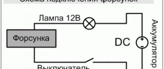
To monitor the alternator output voltage, connect a car lamp to an open circuit from terminal 30 on the alternator (the point of contact with the thick wire leading to the positive terminal of the battery or starter).
Then connect the multimeter in = 20 V mode with the red probe to terminal 30 of the generator, and the black probe to the insulated terminal on the engine or car body. Start the engine. The multimeter reading should not exceed 15.5 volts each time the accelerator pedal is pressed. Otherwise, continuing to operate the generator may be dangerous to the vehicle's electrical system.
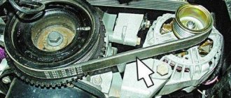
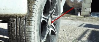
When inspecting the alternator belt, the degree of tension should be assessed. A simple way to do this is to press the strap with your finger.
The size of the deviation should be between 0.5 and 1 centimeter. At the same time, check the belt wear. The generator must be removed for repair to determine the cause of the generator failure.
How to check for serviceability?
Before diagnosing problems with injection and carburetor cars, you must start the engine and let it run for a few minutes. Then, pressing the gas pedal, you need to increase the number of crankshaft revolutions to 3 thousand/min.
To create a simulation of driving in normal mode, enable:
- driving lights;
- rear window heating systems;
- stoves.
Diagnostics with a multimeter:
- The tester is used to measure the voltage at the battery terminals. This parameter will be 13.2 volts in model 9402.3701 and 13.6 V for 37.3701. If, during diagnostics, without removing the voltage at the battery terminals, the obtained value turns out to be different, this indicates a break or short circuit in the windings of the device. The voltage regulator and brush assembly may also fail. Sometimes the problem is oxidation of the contact components of the field winding.
- To ensure that the regulatory mechanism is working, all energy consumers are switched off. Only the high beam optics remains switched on, after which the voltage measurement procedure is repeated. This parameter should be in the range from 13.2 to 14.7 volts for model 94.3701. In the 37.3701 electric generator, the resulting value will be from 13.6 to 14.6 V.
- If the control element on model 9402.3701 is removed, it can be checked by connecting a light source to the brush mechanism. In particular, between its elements. The lamp should be rated at 1-5 watts and 12 volts. The DC power supply is connected to the D+ pins and device ground. Diagnostics is performed first by activating the voltage at 12 volts, and then at 15-16 V.
- In the first case, the light source should work, but in the second, it should not. If it is activated when 12 and 15 volts are supplied, then a breakdown must be looked for in the regulatory device. If there is no combustion, the cause should be checked for a break or broken contact between the brush elements and the terminals of the device. The regulator itself is changed to restore the generator's functionality. To test the device 37.3701, the light bulb is connected to contacts B and C, this is a plus, as well as to ground.
- Checking the valves of the rectifier device is carried out by disconnecting the cables from the battery, generator unit, and also the regulator contact. The positive terminal from the battery is connected through a light source to the B+ output on the generator device 9402.3701. If this is model 37.3701, then it must be connected to output 30. The negative contact is ground, connected to the housing. If, as a result of the actions performed, the light source started working, then the problem is a short circuit (in both blocks).
- Diagnosis of a similar problem on positive valves is carried out by connecting the positive contact of the battery to the B+ output (for model 37.3701 - contact 30). The connection is made through the light source. The negative contact goes to the output of the phase winding of the stator mechanism (you can connect to any). The inoperability of one or more positive valves will be indicated by activation of the light bulb.
- The procedure for diagnosing a short circuit on the negative contacts of the element is performed by connecting the positive terminal of the battery to the phase winding of the stator mechanism. There should be a light bulb on the electrical circuit, and the negative terminal goes to the housing of the generator set. If the lighting device lights up, this indicates damage to the negative valves or a short circuit of the stator mechanism to the body of the automobile electric generator.
- To prevent short-circuiting of the windings, the assembly is dismantled from the machine, after which the elements are disconnected from the regulator and the rectifier unit. Using a light source or an ohmmeter, parts are checked for short circuits. The valves of the generator device can be diagnosed with a tester; this does not require connecting a battery or a light bulb.
- To check additional diode elements, the positive terminal of the battery is connected to output D through a light source. In model 37.3701, the connection must be made to pin 61. The negative terminal goes to the output of one of the phase windings of the stator device; you can use a screw to secure the rectifier assembly. If the light source lights up, this indicates damage to the diode elements.
- To determine whether the valves are broken, you need to check the output current; this parameter should not fall as a result of the load. But such a problem may be caused by damage or short-circuiting of the windings of the generator unit.
- To diagnose each diode element, you will need a tester or test light. To do this, the rectifier assembly will have to be dismantled. If this device breaks down, it must be replaced as an assembly. It is possible to replace individual valves, but the main elements require re-pressing in the holding device. Performing this operation requires caution and skill from the car owner.
The windings of a stator or rotor mechanism can only be diagnosed using a flaw detector or electronic oscilloscope; the test consists of monitoring voltage curves.
The “Avto-blogger” channel described in detail the procedure for examining a car’s generator unit.
Possible faults
If the node does not work or functions incorrectly, you need to find the cause of the problem:
- When the ignition is activated, the indicator light on the dashboard does not light up. Perhaps this symptom was caused by a faulty fuse. The problem may be damaged wiring. It is necessary to check the electrical circuits and safety devices. Wiring testing is carried out using a tester.
- The LED indicator on the device does not light up, but the battery is discharged, all other control devices are working normally. A possible problem is a short circuit of the diode elements on the bridge or poor contact on the excitation winding. The cause of the problem may be a malfunction of the relay, failure of the brush mechanism, or damage to the wiring from the generator to the dashboard. All failed components can be repaired or replaced yourself.
- The battery indicator light on the dashboard lights up when the engine is running, the battery may be overcharged. It is necessary to diagnose the regulatory device; the problem may lie there.
- When the car engine is running, the battery indicator lights up too brightly or only at 50%. It is necessary to diagnose the drive belt; the problem may be that it is worn out or weakened. To eliminate the malfunction, the belt must be tightened or replaced. The reason may be a short circuit of the stator winding to ground or damage to the electrical circuit. Sometimes the reason lies in faulty diodes or disconnection of the rotor mechanism from the slip rings.
- A whistle comes from under the engine hood. The noise may appear when the power unit is started and disappear after a few minutes, or it can be heard constantly. The problem is due to wear on the drive belt. This product must be replaced.
- A strong hum-like noise may indicate a worn generator set bearing. Sometimes this symptom is associated with a short circuit of the stator winding to ground or a short circuit of one of the diodes.
- At night, when the optics are activated, you can see that the headlights burn dimly. But when you press the gas pedal, their brightness is restored to the required level. The voltage regulator device needs to be checked.
Channel “Tora 18” talked about the main malfunctions typical of automobile generator sets.
How does the generator work on the VAZ 2109?
On the VAZ 2109, a generator is constantly installed according to the traditional scheme, which plays an incredibly important role in the power supply system. That is, it makes it possible to work correctly. In addition, it charges the battery. Therefore, during operation of the vehicle, it is necessary to constantly monitor the operating process of the generator. Therefore, it is not recommended to wait until suddenly a special light comes on on the dashboard. It is necessary to regularly carry out diagnostics, then immediately replace or repair broken elements.
Generator circuit 37.3701
The generator, as a rule, consists of such main housing components as: an armature, two covers, a stator and a pulley with a fan. There are windings on the stator as well as the rotor. The first is divided into three parts, because at the output you need to get a voltage consisting of three phases. There is only one reason - this scheme makes it possible to get rid of all kinds of pulsations. This means that the efficiency of the device will be much higher. However, all this in turn imposes certain requirements. The basis of the work is that the rotor moves inside the stator winding. There is a coil on it, powered by the on-board transport system. As a result, a moving magnetic field appears around the rotor. Therefore, for efficiency it is imperative to ensure voltage stability on the rotor winding. Which is precisely an important condition for the operation of the generator set, which comes in two different types.
Generator connection diagram 37.3701
One part of the machines operates on a 37.3701 series V-belt drive, and the second uses a 94.3701 series poly-V-belt drive. However, in any case, all of them are necessarily located in the front part of the car, that is, on the internal combustion engine.
Technical specifications 37.3701
| Maximum output current at 13 V and 5000 min-1, A | 55 |
| Adjustable voltage limits, V | 14,1+0,5 |
| Maximum rotor speed, min-1 | 13000 |
| Engine/generator ratio | 1:2,04 |
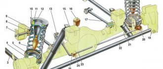
What does generator 37.3701 consist of: 1 – capacitor; 2 – voltage regulator assembled with brush holder; 3 – terminal block for additional diodes; 4 – insulating bushings; 5 – rectifier block; 6 – contact bolt; 7 – stator; 8 – rotor; 9 – spacer sleeve; 10 – inner bearing mounting washer; 11 – drive side cover; 12 – pulley; 13 – outer bearing mounting washer; 14 – coupling bolt; 15 – front rotor ball bearing; 16 – bushing; 17 – cover from the side of the slip rings; 18 – buffer sleeve; 19 – clamping sleeve.
But there are also some differences here. So in the first series, the VAZ 2109 generator device consists of a large number of different components:
- bushings,
- capacitor components,
- stator mechanisms,
- rotor windings,
- pulley,
- rear bearing of the rotor shaft,
- rear cover of the unit,
- fixing bolt,
A more complex design is the second series, which has many more of the above parts:
- bushing,
- brush assembly holder,
- capacitor device,
- shaft,
- coupling bolt,
- cone washer,
- fixing device for positive diode elements of the rectifying mechanism,
- fixing negative diodes and the like.
The range of the first model is often approximately 120 thousand km, but the second one is a little more, and all thanks to the slip rings, which have a smaller diameter. It all depends on the technical characteristics. As well as proper switching on of the electric generator.
Since each brand of this device is different:
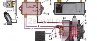
Generator 37.3701: 1 – cover on the side of the slip rings; 2 – rectifier block; 3 – rectifier block valve; 4 – screw for fastening the rectifier unit; 5 – contact ring; 6 – rear ball bearing; 7 – capacitor; 8 – rotor shaft; 9 – output “30” of the generator; 10 – output “61” of the generator; 11 – voltage regulator; 12 – terminal “B” of the voltage regulator; 13 – brush; 14 – stud securing the generator to the tension bar; 15 – pulley with fan; 16 – rotor pole piece; 17 – spacer sleeve; 18 – front ball bearing; 19 – drive side cover; 20 – rotor winding; 21 – stator; 22 – stator winding; 23 – rotor pole piece; 24 – buffer sleeve; 25 – bushing; 26 – clamping sleeve.
When using 37.3701 , when turning the ignition key, voltage is connected through a special light bulb on the instrument panel, as well as resistors. When the internal combustion engine is started, the voltage goes to the excitation winding of the motors located on the rectifier block (the main voltage goes to the output of the regulator, the current does not pass through a special light bulb, as a result it does not light up).
Generator 94.3701: 1 – casing; 2 – output “B+” for connecting consumers; 3 – noise suppression capacitor 2.2 μF; 4 – common terminal of additional diodes (connected to the “D+” terminal of the voltage regulator); 5 – holder of positive diodes of the rectifier unit; 6 – holder of negative diodes of the rectifier unit; 7 – stator winding terminals; 8 – voltage regulator; 9 – brush holder; 10 – back cover; 11 – front cover; 12 – stator core; 13 – stator winding; 14 – spacer ring; 15 – washer; 16 – conical washer; 17 – pulley; 18 – nut; 19 – rotor shaft; 20 – front rotor shaft bearing; 21 – beak-shaped pole pieces of the rotor; 22 – rotor winding; 23 – bushing; 24 – tension screw; 25 – rear rotor bearing; 26 – bearing sleeve; 27 – slip rings; 28 – negative diode; 29 – positive diode; 30 – additional diode; 31 – pin “D” (common pin of additional diodes)
When using 94.3701 , approximately the same thing happens (as soon as the ignition is turned on, the voltage goes through a special light bulb to the regulator output).
It is important to constantly pay attention to ensure that everything is working properly. So the light bulb should light up immediately when you turn the key. And as soon as the internal combustion engine is started, it will turn off instantly. But if it does not immediately stop working, then the generator is faulty.
How to repair it yourself?
The restoration procedure consists of several stages:
- First you need to dismantle the unit.
- Then it is disassembled, at this stage the unit needs to be repaired.
- After this the assembly is performed.
- At the final stage, the node must be installed and connected.
Required Tools
Before completing the task, you need to prepare:
- vice;
- removable tool for bearing devices;
- set of wrenches;
- screwdriver set.
Removing the generator
The dismantling procedure is performed as follows:
- The cables are disconnected from the generator set. They are usually made in red insulation and include 2 groups of conductors. One of them consists of two cables and is fixed with a nut to a bolt on the rear wall of the unit. The second group includes one cable and is connected to the terminal of the generator device via a contact element. It is also located on the back wall of the unit.
- To remove the generator unit from the power unit, you need to unscrew two nuts and a screw. First, the fastening element installed on the drive belt tensioner bar on top of the unit is unscrewed. Then the screw is unscrewed, which secures the part itself to the engine block of the machine, this element is dismantled. At the final stage, the nut is removed from the screw securing the bracket to the internal combustion engine.
- The fixation part is located at the bottom of the power unit, directly under the generator set. After the nut is removed, the drive belt must be removed from the shaft.
- The screw securing the assembly must be pushed to the left so that it comes out of the bracket. The element is pressed all the way into the vehicle body or into the mud shield of the unit.
- Then the two screws located on the right wheel side are unscrewed. They fix the dust protection of the generator set to the car body.
- If the bolt rests on the elements of the machine body, apply a little pressure to the motor. At the same time, the fastening part is removed.
User Sanya Kiselev spoke in detail about the procedure for dismantling the installation from the Nine engine.
Disassembly and repair
After the unit has been removed, all parts are dismantled and the VAZ 2109 generator is restored to functionality:
- Using a 19mm wrench, loosen and unscrew the nut on the rotor pulley. It is used to fix the impeller. To perform this task, the generator unit must be clamped in a vice. Using a screwdriver, the impeller is held from turning. Using a wrench, unscrew the nut counterclockwise.
- The impeller of the device is fixed with a pin. After dismantling it from the pulley, it is necessary to remove this element and put it aside; it cannot be lost. When unscrewing the nuts, it is recommended to sketch the location of the components.
- Then the generator unit is turned over with the back cover up. Using a size 8 wrench, unscrew the four nuts.
- The pins are removed and the front part of the device body is dismantled. The front bearing element is also located here; it is fixed using plates. To dismantle them, you need to unscrew the nuts that secure the elements.
- Using a special puller, the bearing device is removed from the landing site. If you don’t have a tool, you can use a hammer and a mandrel of the appropriate size. The use of a wooden board is allowed.
- The spacer sleeve is removed from the rotor mechanism pulley.
- This unit is removed from the rear cover of the generator device.
- The leads of the stator winding are disconnected from the rectifier. To do this, you need to unscrew the nuts that secure them. After dismantling the fastening elements, the bolts are unscrewed. They record the conclusions themselves.
- Insulating pads are located on the bolts. The stator winding must be removed from the unit housing.
The next step is to remove the diode bridge; this requires the following steps:
- Use a wrench to unscrew the nut that secures contact number 30.
- Next to this pin there is a block with a plug. This element must be dismantled. But you should first release the fastener using a small flat-head screwdriver.
- The latch is disconnected from the inside. Then the block with wires is pushed inside. The plug should remain on the cover. The diode bridge is dismantled from it.
- The next step requires a vice. The rotor mechanism must be clamped into the equipment so that the rear bearing device is located on the top.
- Using a puller, the part is dismantled. To do this, you need to put the tool on top of the assembly and pull the bearing element off the pulley.
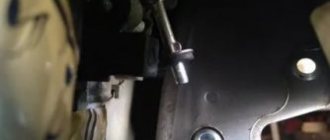
Unscrewing the generator impeller
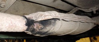
Disconnecting pin 30, connector and dismantling the diode bridge
Removing the bearing device from the pulley
After disassembling the elements of the generating set, replacing the failed components:
- To change bearing parts, you need to check the markings of the elements. Similar spare parts are purchased at the auto store. Even if the bearings are visually intact, it is recommended to replace them. The parts are not interchangeable, so when purchasing, be sure to follow the markings.
- The same goes for the diode bridge. The markings are rewritten from the part, only after that the spare part is purchased. If there is visible damage to this device or metal oxidation has occurred, the unit must be replaced. It is fixed to the generator housing with four nuts. The diode bridge is located at the back, on the inside.
- A visual diagnosis of the front cover of the generating set is carried out. If there are cracks or other damage, the casing must be replaced. When performing visual diagnostics, it is important to pay attention to the fastening elements.
- The diameter of the seat for the bearing parts in the front cover is measured. If the socket for their installation is more than 4.2 cm in diameter, the cover must be replaced.
- Then a visual check is made of the rear of the unit. If there is damage on it in the form of cracks, it must be replaced. Wear or breakage of the seating area under the bearing element is not allowed. If such damage occurs, the cover must be replaced.
- Visual diagnostics of the internal surface of the stator device is carried out. Scratches and other defects resulting from touching the anchor are not allowed. If wear is detected, the bearing elements or the generator set cover are replaced.
The winding of the dismantled rotor mechanism is checked, the task is carried out as follows:
- It is necessary to visually inspect the slip rings. These elements must be replaced if defects are found. We are talking about signs of wear, scuffs, scratches, etc. In principle, the rings do not need to be replaced if the damage is minor. But then they will have to be sanded, for this you will need fine-grained sandpaper.
- If damage to the elements cannot be removed with sandpaper, you can try turning them on a lathe. When using the equipment, it is necessary to remove a minimum layer of metal and then sand the surface.
- Using a tester, the resistance value of the winding of the rotor mechanism is checked. To do this, the device must be connected to slip rings. If the diagnostics show that the resistance tends to infinity, this indicates a break inside the winding. To correct the problem, you will need to replace the rotor mechanism.
- Using a test lamp, a diagnosis is made of the absence of a short circuit in the winding of the anchor device on the housing. To do this, you need to activate the light source by connecting it to the battery. One contact is connected to the body of the anchor device, and the other is connected to each ring in turn. The indicator light should not light up when the rotor is operational. If it is activated, this indicates a short circuit in the winding, then the armature will need to be replaced.
Vyacheslav Lyakhov spoke in detail about performing diagnostics, as well as repairing the unit in the VAZ 2109 car.
Generator assembly
If you managed to disassemble and repair the unit, then after completing the work you will need to put it back together:
- The rear bearing device is installed at the landing site, on the shaft. A wooden board and a hammer are used to complete the task. The bearing is carefully driven in so as not to damage the part. To do this, just hit it several times.
- If the diode bridge was dismantled, it must be reinstalled. The device is located in the back cover of the case.
- The protective casing is then installed on the anchor device so that the bearing element is completely seated. To simplify the action, you can use a hammer. Light blows on the cover clog the bearing; it must be placed on the pulley. The same part installed on the front cover is replaced and fixed using plates.
- Then the generator device is dismantled from the vice. Before installing the front cover on the assembly, the spacer ring is mounted on the pulley. This part should be located between the thrust recess and the front bearing device.
- The cover is installed from the front, the stud nuts are tightened using the crosswise method. This will ensure more uniform tightening of the fastening elements.
- The stud is installed in the recess on the shaft of the anchor device. Then the impeller is installed, the element is clamped with a nut.
- At this point, the assembly procedure for the generator device can be considered complete. All that remains is to install the voltage regulator with brushes at the landing site.
Evgeny Bragin described the assembly procedures for the “nine” unit, indicating all the nuances of this process.
Installation and connection
Installation of the generator unit is carried out in the reverse order; when performing this task, it is important not to forget to connect the wire to the control device:
- A fixation bracket is screwed to the installation. A wrench is used.
- The bracket is then screwed into place with the generator set. When performing this task, you do not need to tighten the nut all the way.
- Self-tapping screws are used to secure the unit's dust protection.
- The drive belt is being installed on the generator set pulley.
- The tensioning element strip is being installed.
- The drive belt is tensioned. When performing this task, it is important that the deflection of the product is about 1-1.5 centimeters. When tightening the belt, it is necessary to tighten the nut on the tensioner bar. Then this element is clamped on the bracket until it stops.
After the installation is completed, you need to connect the terminal blocks to the generator device. When performing the task, you need to make sure that the clamps are disconnected from the battery. There should be a total of three wires connected to the unit. Paired cables are secured with nuts to a stud located on the back cover. A male connector must be installed in a female connector.
Then the terminal clamps are installed on the battery, and the power unit is started. The generator unit supplies the voltage required for full operation of all machine devices.
To be sure that the unit is working properly, you need to use a voltmeter to diagnose the voltage that the unit produces.
Generator set connection diagram
Causes
By providing voltage, the generator exhausts its resource. Its individual elements wear out over time, resulting in the following malfunctions:
- brush abrasion;
- breakdown of both stator and rotor windings;
- loose or broken drive belt;
- burnout of the diode bridge.
The reason that the generator does not charge the battery well also often lies in a simple break in the wiring or poor contact at the connection points.
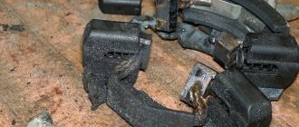
If the machine has been in use for a long time, then the graphite brushes should be inspected first. They are always the first to fail. As wear occurs, contact with the rotor rings is lost and the generator ceases to perform its functions. In this case, it is necessary to replace the damaged element with a new one. The price of the brushes is low, and they are sold in virtually any specialized retail establishment.
Bridge failure quite often occurs due to incomplete loss of contact with the stator winding. As a result, the resistance increases, the conductors heat up and the diodes burn out. The entire unit is replaced.
Poor operation of the generator is also caused by a break or excessive stretching of the drive belt. Over time, it loses its elasticity and sags. A new one is installed to replace the damaged one. It is not difficult to check the degree of tension - just press on it with your hand in the central part.
The design of the generator allows, if necessary, to replace any of its main elements. Therefore, if there is a break in the rotor or stator windings, they are replaced with new ones.
Safety precautions when working
Nuances that must be taken into account when repairing a VAZ 2109 generator:
- All control and adjustment work related to diagnosing the unit with the engine running must be carried out in a ventilated area or outdoors. If it is a garage, it is recommended to open the doors or provide good ventilation.
- Before carrying out the task, you need to button up your sleeves if the work is performed in a shirt. All hanging ends of clothing should be removed to prevent them from getting caught on the operating pulley.
- To carry out repairs, a specialized tool is used.
- The generator must not be allowed to fall after it has been removed during transportation to the machine. This can lead to complete failure of the unit.
- Repairs should only be carried out using serviceable, clean and oil-free tools.
- If the nuts are rusty and difficult to unscrew, it is recommended to treat the elements with kerosene or WD-40 before turning them out. Dismantling is carried out with preliminary tapping with light blows of a hammer.
- The vehicle is inspected using a 36-volt light bulb. If the diagnosis is performed in a ditch, a 12 V light source will be required. It is important that the light bulb is equipped with a safety net.
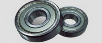
Generator bearing wear
The car generator has two bearings. One of them is fixed to the rotor shaft, the other is pressed into the central part of the cover. A humming or whistling sound on the side of the generator when the engine is running is a sure sign that one of the bearings has failed. A related symptom may be heating of the generator housing. When you notice these symptoms, hurry up and replace the bearings. Failure to comply with this rule will lead to distortion of the rotor shaft or jamming with all the ensuing consequences.
You can check the bearings by removing the alternator belt and turning the shaft by hand. If the impeller rotates easily, without jerking or play, the bearings will continue to work. If rotation is difficult or the shaft has play, replace the bearings immediately.
Only two devices allow the vehicle's ignition system to function. Battery and generator. They act in tandem, complementing each other.
Each of these devices can operate separately from the other for a short time. A damaged generator may run for some time before the battery dies.
Also, the ignition spark can only be maintained by the generator, but there is a problem with the first start of the engine - without the battery, the crankshaft will not rotate.
Moreover, smooth operation will be interrupted by the voltage regulator.
Repair costs
The approximate cost of spare parts is shown in the table.
| Name | Price, rub |
| Price of a set of bearing elements | Around 150 rubles. |
| Generator diode bridge | 200 rub. |
| Charging relay | About 150-200 rub. |
| Removal tool for bearing elements | Around 100-200 rubles. |
| Prices are relevant for three regions: Moscow, Chelyabinsk, Krasnodar. | |
Loading …
Replacing generator brushes without removing the generator
This method is used when the problem is definitely in the brushes and removal and inspection of the generator is not required.
- Disassemble the car's generator. But do not remove it completely (do not unscrew the generator mounting bolts).
- Clean the brush holder socket. It is better to do this by blowing with compressed air.
- Clean the brush holder with a cloth.
- Remove the brushes.
- Clean all contacts.
- Check the elasticity of the spring. If it is insufficient, replace the spring.
- Polish the slip ring if it has visible defects.
- Install the brushes and reassemble the generator in reverse order.
Replacing alternator brushes on a VAZ 21099 car is not at all difficult. Any car owner who prefers not to take their vehicle to a service center, but to carry out the maintenance themselves, can handle this.
For proper repairs, you only need detailed instructions given in this article and a tool that every car owner has.
Generator brushes can fail from time to time and require replacement. If this happens, you can independently carry out work in this area and restore the functionality of your vehicle.
Before starting work, it is very important to prepare in advance all the necessary details that may be needed to complete the action.
Disassemble the car and remove the alternator to make work easier. Having removed the generator, you can proceed directly to repairs. After completing all the work, install everything in its place and secure it as it should.
If you have a question about how to properly repair brushes, it is best to study the video material, which explains in detail how to quickly get the job done quickly and efficiently. The specialist also explains the main nuances that you need to pay attention to when carrying out the work. That is why, as statistics show, there are no problems after the work is completed.
The popular VAZ 21099 car in Russia has a short service life, but at the same time a simple design. A fairly common malfunction on this vehicle is excessive wear of the brushes in the generator. They definitely need to be replaced, because otherwise the generator will stop working normally and the engine will stop starting.