Complete electrical diagram of the VAZ 2114 with decoding
The complete package of electrical equipment of the VAZ 2114 can be divided into two types. The fundamental differences are due to changes in equipment depending on the year of manufacture and equipment of the car. In this case, the entire drawing can be divided into several zones.
- The engine compartment is responsible for providing voltage to sensors and instruments located directly inside the engine compartment.
- Salon compartment. The part is primarily used to connect the front and rear compartments.
- Instrument panel assembly. The pinout is displayed directly on the controls and dashboard. All elements of the on-board network are combined here and connected to buttons or indicators.
- Stern joint. The small module combines chain elements located at the rear of the machine. Typically, the segment is subject to frequent damage, which is due to the constant transportation of goods in the luggage compartment. When moving over obstacles, loads can damage sensitive equipment.
You can also separate small units – these are door units, windshield wipers and others. For ease of perception, each beam is considered separately.
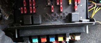
VAZ 2114 instrument panel pinout
The terminals of all vehicle equipment are concentrated here. Due to the fact that the unit is located under the dashboard and is subject to constant condensation or fogging, some users treat it with hot melt adhesive. Even a thin coating can reliably protect the device from water ingress.
Elements are connected to devices or controls:
- 1 – switch key for heated rear glass;
- 2/6 – fog light switches, for rear/front module;
- 3 – plastic block for activating head optics and turn signals;
- 4 – fuse block;
- 5 – wiper mode switch;
- 7 – on-board system indication;
- 8 – supply voltage to the additional harness;
- 9 – dashboard;
- 10 – “male” for powering the on-board computer;
- 11 – terminal to the ignition device;
- 12 – for door wiring;
- 13/14 – fuses;
- 16 – ignition break;
- 17 – stove motor;
- 18 – secondary resistance of the stove;
- 19 – current supply to the ignition unloading relay;
- 20 – protective relay for rear fog lights;
- 21 – starter fuse relay;
- 22 – remote socket for a portable lamp;
- 23 – power supply for the cigarette lighter;
- 24 – for illumination of the glove compartment;
- 25-27 – illuminators;
- 28 – stove switch;
- 29 – tidy lighting with rheostat;
- 30 – stop switch;
- 31/32 – horn/hazard warning switch, respectively;
- 33 – backlight of the stove panel;
- 34 – fuse;
- 35 – protective relay for seat heating elements;
- Ш1/4 – mounting block jumpers;
- X1/2 – dashboard controls;
- A – protective ground output (usually black).
Emergency warning button VAZ 2114: review and replacement options
The original, factory-installed emergency lights of the VAZ 2114 are the subject of outrage among many motorists. The reason here lies in the fact that it is not installed in its usual place - on the panel, but is mounted on the side of the steering column casing.
This arrangement makes it much more difficult to quickly use the button while driving (for example, to say “thank you,” which is common for most drivers). It is for this reason that many are thinking about transferring it.
It should be noted right away that the emergency warning button of the VAZ 2114 has non-standard dimensions, as a result of which it will not be possible to simply move it from the steering column to the Euro panel - it simply will not fit. And on the casing itself, in the place where the button was located, there will be a large hole.
It is for this reason that replacement should be performed in this order:
- dismantling the original emergency gang;
- dismantling the column casing;
- installation of a new casing;
- connecting the new euro button to the network;
- mounting the button on the panel.
Electrical equipment of the front of the car
The following is a breakdown of the front cable bundle, excluding fog lights:
- 1 – output terminals of the starter contact group;
- 2 – battery, connection of power cables;
- 3 – standard “father” of the generator;
- 4 – blocks for connecting the power conductors of the battery and generator to the front assembly of electrical equipment;
- 5 – part of the fuse mounting block;
- 6 – standard horn;
- 7 – sensor that measures the temperature of antifreeze in the power plant;
- 8 – standard sensor for measuring the washer fluid residue in the tank; when activated, the corresponding indicator on the device lights up;
- 9/10 – left and right headlights, respectively;
- 11 – external thermometer;
- 12 – standard reverse gear lamp switch;
- 13 – drive of the electric fan of the generator;
- 14 – connector to the ignition system module;
- 15 – in the VAZ 2114 scheme the injector is not used, it is used only for the carburetor;
- 16 – electronic brake fluid level sensor; in case of a critical drop, an exclamation mark lights up on the instrument panel;
- 17 – built-in oil level sensor in the crankcase compartment of the power plant; when activated, the red light on the instrument panel lights up;
- 18 – similar for the engine cooling system;
- Ш5-8 – mounting block connectors;
- A1/2, B1/2 – grounding terminals.
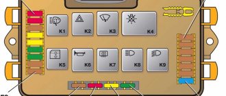
Relays and fuses VAZ 2114
- F1 for 10 Amps (A) rear fog lights and rear fog light warning lamp.
- F2 for 10 A turn signal lamps, turn signal relay, hazard lights, hazard warning lights.
- F3 7.5 A lamps for interior lighting (both) and trunk, ignition lighting, powertrain control system control lamp, brake lamps, computer, if available.
- F4 20 A carrier, relay and rear window heating element.
- F5 20 A horn and its relay, cooling fan.
- F6 30 A power windows and their relays
- F7 30 A motor for heater, headlight cleaner, windshield washer, cigarette lighter, glove compartment light bulb, rear window heating relay coil.
- F8 7.5 A right fog lamp.
- F9 7.5 A left fog light.
- F10 at 7.5 A left side marker, lamp signaling the inclusion of the side light, lamps for illuminating the sign, engine compartment, illumination of switches and instruments, instrument lighting switch.
- F11 at 7.5 A right side.
- F12 at 7.5 A right low beam.
- F13 at 7.5 A left low beam.
- F14 for 7.5 A left high beam and a light indicating that the high beam headlights are on.
- F15 at 7.5 A right far.
- F16 30 A - a light indicating insufficient oil pressure, brake fluid level, engagement of the parking brake, low battery, instrument cluster, relay for monitoring the health of lamps, indication of control systems, reversing lamps, turn indicators and their relays, as well as an alarm if turning mode is turned on, computer, generator excitation winding is turned on at the moment the engine starts.
Wiring diagram VAZ 2114 injector: decoding of rear harness contacts
Here are the conclusions of the equipment located in the rear of the vehicle:
- 1 – output of the mounting unit;
- 2 – windshield heater;
- 3 – electric drive of the rear wiper gearbox;
- 4 – diodes for illuminating the stern license plate;
- 5 – license plate illuminator directly, some users connect diode strips here for better lighting;
- 6/7 – illuminated direction indicators, for the left and right sides, respectively;
- 8 – lamp for individual illumination of useful space;
- 9 – interior lighting lamp, usually located in the ceiling, above the steering seats;
- 10 – handbrake lever position indicator;
- 11/12 – left and right side lighting lamp;
- 13 – power supply to the additional brake light indicator;
- 14-17 – group of interior lighting switches located in the door pillars;
- Ш9 – terminal block of the fuse mounting device;
- A1 – license plate grounding;
- A2/7 – standard grounding points.
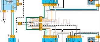
Scheme for switching on headlights, side lights and turn signals for VAZ-2113, 2114 and 2115
Headlight switching diagram for VAZ-2113, 2114 and 2115
Scheme for switching on headlights and fog lights:
1 – headlights; 2 – mounting block; 3 – headlight switch; 4 – ignition switch; 5 – external lighting switch (fragment); 6 – fog lamps in the internal rear lights; 7 – fog light switch with control lamp; 8 – indicator lamp for high beam headlights in the instrument cluster; K8 – headlight high beam relay; K9 – relay for low beam headlights; A - the order of conditional numbering of plugs in the headlight block; B - to power supplies
Scheme for switching on the side lights of VAZ-2113, 2114 and 2115
External lighting switching diagram:
1 – side light lamps in headlights; 2 – engine compartment lamp; 3 – mounting block; 4 – engine compartment lamp switch; 5 – ignition switch; 6 – external lighting switch (fragment); 7 – indicator lamp for external lighting in the instrument cluster; 8 – side light and brake light lamps in the external rear lights; 9 – license plate lights; 10 – instrument lighting regulator; 11 – brake light switch; 12 – on-board control system unit; K4 – relay for monitoring the health of lamps (contact jumpers are shown inside the relay, which must be installed in the absence of a relay); A - to power supplies;
Schematic diagram of the VAZ 2114 stove: a separate line responsible for powering the windshield wiper
A small cable harness responsible for powering and controlling the cabin air supply box. There is also a power supply for the windshield wiper:
- 1 – part of the installation site exit;
- 2 – sensor for monitoring lubricant pressure in the crankcase compartment of the power plant;
- 3 – power lines of the aft windshield washer motor;
- 4 – voltage to windshield washer drives;
- 5 – diagram of the electric motor for windshield wipers;
- Ш11 – terminal for connection to the installation site;
- A – grounding terminals of the wiring section.
Electrical connection diagram for VAZ 2114, additional segment
Here are grouped auxiliary equipment that is not related to the power plant or on-board computer of the car:
- 1 – contact group of wiring from the doors to the instrument panel block;
- 2 – a similar terminal intended for connecting heated seat devices for the driver and front passenger;
- 3/4 – central locking drive, sections of the front left and right doors, respectively;
- 5/6 – contact blocks of the front right and left speakers, respectively;
- 7 – electronic central locking control unit;
- 8/9 – connecting door parts of electrical equipment to the auxiliary left beam;
- 10 – terminal for connecting the standard speaker system;
- 11 – “mother” of doors to the right wiring harness for connecting electrical equipment;
- A1 – connection of grounding electrical wiring.
Physically, the output is connected to the dashboard, with a contact group located near the hood opening handle. The corresponding fuse is also located here.
How to install the euro button?
In order to install a Euro button instead of the one installed at the factory, you will need to purchase the following electronic components:
- Euro emergency warning button for VAZ 2114.
- Block for its installation.
- Relay type HLS4453.
- Block for the specified relay (you can do without it, but the block greatly simplifies assembly).
- About 2 meters of wire with a cross section of 0.5 mm square. or a little bigger.
- Terminals in the amount of 6 pieces.
- Insulating tape.
The first thing you need to do is connect the new Euro button to the electronic relay.
This must be done according to the following scheme:
All wires extending from the new button to the relay should be well secured (preferably soldered). And terminals should be attached to the ends of the wires extending from the relay to the old button (or rather, to its block).
Despite the fact that the connection using terminals is quite strong, it is still recommended to solder it by applying a small amount of solder to the wire entry point - this will help to significantly increase reliability and improve contact.
After the Euro emergency light 2114 and the relay are connected, you will need to remove the old button. To do this, first remove it from the socket and then disconnect it from the electronic block. The block itself should be moved to the europanel (where the new button is supposed to be mounted), and then 6 terminals coming from the relay should be connected to it. This must be done according to the numbering of the wires extending from the relay, which is shown in the above diagram.
On the block itself, if placed with the empty sockets facing down, the numbering will look like this (clockwise): 4-3-2-1-8-7.
Then we disconnect the button for turning on the side lights from its block and connect to it the wires coming directly from the button (indicated in the diagram). One goes to the gauge wire (it’s white), the other goes to the negative wire (it’s entirely black). All connections must be well twisted and insulated. After this, we connect the size button back to the block.
The last thing that remains to be done before the Euro emergency brake on the VAZ 2114 is finally installed in its place is to remove one (any) plug on the Europanel, bring the block connected to the system to it and simply insert the button into it.
If an on-board computer is installed in the car, then before installing a new hazard warning button, it must be turned off. It is not necessary to turn off other electronic devices.
VAZ 2114 wiring diagram: section of the right front door
The cut is a simplified concept due to the minimal amount of equipment. The most budget version is completely absent.
- 1 – “mother” of the rear harness, suitable for the door wiring;
- 2 – power supply to the electric motor for the front passenger window;
- 3 – terminal block to the standard door speaker;
- 4 – door lock servo motor (part of the central lock);
- 5 – power switch and power window drive mode switch;
- A – grounding bus.
Wiring diagram VAZ 2114: driver's door
A larger section of standard on-board wiring:
- 1 – contact group for connecting to the wiring of the additional bundle;
- 2 – similar output to the aft left beam;
- 3 – electric window motor drive;
- 4 – standard output of the block to the front speaker of the standard acoustic system;
- 5 – door lock drive;
- 6/7 – power window control buttons, for left and right, respectively;
- A1 – standard protective grounding terminal.
Wiring diagram VAZ 2114 injector - a separate section of seat heating equipment
A specially dedicated section of on-board wiring responsible for powering, activating and adjusting seat heater devices. Here is a detailed description of all structural elements:
- 1 – driver’s seat heater;
- 2 – output to the terminal block of the dashboard;
- 3 – separate connector for the driver’s door, wire supply to the control button;
- 4 – heating element of the front passenger seat;
- 5/6 – adjustment key for the element specified in paragraphs No. 1 and 4;
- A1 – grounding wire, fastened with a bolt to the car body.
Pinout of on-board computer VAZ 2114
In standard drawings of electrical equipment, the BC block section is missing due to its uselessness. Initially, it is assumed that the motorist will not independently repair or maintain the complex control unit. But some users still take risks and install the system themselves. In older versions of cars, such a module is missing or insufficient for comfortable operation of the car in its modern form.
To connect wires to the module, you will need to buy a standard 9-pin header and connect the following wires to it:
- 1 – green wire comes from the fuel consumption sensor;
- 2 – the ignition cylinder is powered through an orange cable;
- 3 – power core from the battery, usually a red wire with a white stripe is supplied;
- 4 – grounding or ground, standard color – black;
- 5 – 6k line, usually a gray wire;
- 6 – Mute – green shell with a red line;
- 7 – the backlight in the standard pinout is output from the marker optics key;
- 8 – a sensor that displays the remaining fuel in the car’s gas tank can be connected directly.
How to prevent electrical equipment breakdowns?
In order for the VAZ 2114 pinout to be required as rarely as possible, the user is required to follow a number of simple rules and recommendations.
- Periodically treat all metal parts with special oil. In this case, it is first necessary to clean the copper patches from oxides and traces of corrosion. Such lesions provoke a deterioration in the transmission of signals, which can be perceived by the car as a breakdown.
- Every 20-30 thousand kilometers, check all equipment and plastic plugs for looseness or reduced fastening rigidity. With constant vibrations typical of vehicles, plastic clamps can fail and cause breakdown.
- Monitor the correct battery charge and the serviceability of the generator. Some machine devices do not work correctly when there is a strong voltage drop.
- Every 40,000 km, check the condition of the wires themselves. With constant use, the braids of the power cores may crack or dry out, which increases the likelihood of a short circuit in the on-board lines. This may also cause a fire.
Step-by-step pinout of the VAZ-2114 window lifter button
A broken window regulator on a car is not only a problem that deprives the driver and passengers of a comfortable ride. And also an incident that can attract the attention of a traffic inspector for violation of traffic rules. Therefore, knowledge of the design features of a car can help the car owner in a variety of situations. This article provides information on how to pin out the power window button on a VAZ-2114, what may cause the mechanism to break down, and the basics for troubleshooting problems in this device.