What determines the performance of the coil?
The classic ignition coil or “bobbin”, as it is also popularly called, is essentially a low-voltage voltage converter from the battery and generator to high-voltage, which is then supplied to the spark plugs. That is, this is a miniature electrical transformer.
The ignition coil is a kind of mini electric transformer
The traditional coil, used on carburetor models of vehicles, consists of two windings. The primary winding receives low voltage pulses, for example 12 Volts. As a rule, this is a small number of turns (up to 150) of thick insulated copper wire. The “primary” has 2 terminals on the coil cover. There are much more turns in the secondary winding - up to 30 thousand, but the wire used is much thinner. One end of the “secondary” goes to the “minus” of the primary winding, the other to the central terminal of the coil. In the center of the windings there is a core that enhances the magnetic field. The coil body is insulated, and its cavities are filled with special oil for transformers.
The fundamental characteristic that indicates the serviceability of almost any coil is the resistance of the windings.
Video Short circuit faults on VAZ 2106
This video talks about the short circuit and its malfunctions on the VAZ 2106 (the author of the video is INGENIEUR).
Operation of a gasoline internal combustion engine is possible only if there is a spark in the combustion chamber. The spark must arrive on time and be strong enough to ignite the air-fuel mixture. The car's ignition system is responsible for this process. It consists of many elements and the ignition coil plays a very important role in the system.
It is very difficult for an electric spark to form in the dielectric environment created by the fuel-air mixture in the combustion chamber. The slightest electrical breakdown under such conditions is possible only in the presence of very high voltage. An electrical impulse of such strength simply cannot occur at a voltage of 12 volts, which is available on the vehicle’s on-board power supply system. The voltage that can cause a short-term spark to appear on the spark plug electrodes must be at least tens of thousands of volts.
To create a pulse of such high voltage, an ignition coil is used. It is designed to convert the voltage of the on-board electrical system at 6, 12 or 24 volts into a short-term pulse with a voltage of up to 30,000 volts. The device transmits an impulse to the spark plug, where a spark appears between its contacts, which is necessary for the working mixture to ignite.
Ignition coils of one configuration or another are installed on all internal combustion engines, without exception, running on gasoline or gas. It is used on all types of ignition systems, without exception – contact, non-contact and electronic.
In principle, the ignition coil is very simple. It has two windings - primary and secondary. A wire with a large cross-section creates the primary winding, and the secondary winding is wound with a thinner wire and the number of turns can be up to 30,000. The primary winding has about one hundred turns. The windings are located around a metal rod - the secondary winding is below, and the primary winding is wound on top of it.
Both windings, like the core, are enclosed inside a dielectric housing, inside of which there is transformer oil. The entire assembly assembly is a step-up transformer. A low voltage current is supplied to its primary winding, and a high voltage pulse is removed from the secondary.
Types of coils and their connection diagrams
With an absolutely identical design, the coils are connected according to different circuits, which determine the type of device:
- common coil;
- custom reel;
- dual or two-terminal.
The simplest and oldest type of coil. Its connection diagram assumes the presence of only one coil that transmits a high-voltage pulse to the distribution device - the distributor. It already distributes high voltage between the cylinder spark plugs, according to their firing order. This connection diagram can be used on all existing types of ignition systems - electronic, contact and contactless.
The operation of the bobbin is based on the process of electromagnetic induction - a high-voltage pulse occurs when small currents pass through the primary winding, exciting a magnetic field in the high-voltage winding, which causes the appearance of a powerful pulse that arrives at the spark plugs.
Custom type coil
Electronic ignition systems can only work with such coils. They differ in connection diagram and appearance - each spark plug has its own coil and this contributes to much better synchronization of the valve timing with the moment of ignition of the mixture of gasoline and air.
How to check the ignition coil with a tester on a VAZ 2106, as well as VAZ 2109 and VAZ 2110 (carburetor)
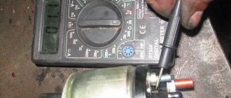
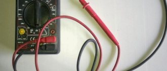
On old VAZs it is not difficult to find a coil. It is located in a freely accessible area, under the hood. To check, you will need a regular multitester, which can be purchased for a small amount in many stores.
Video tutorial on measuring ignition coil resistance
The procedure is as follows:
- Disconnect the negative voltage on the battery. Disconnect the ignition coil wires, loosen the brackets. Clean the reel body. If obvious damage, cracks, etc. were discovered, it is better to immediately replace the device with a new one, since such a coil cannot be used.
- On the tester, turn on the ohmmeter mode. To check the “primary”, install probes or clamps on the side terminals located on the coil body. The tester display will show about 3.07-3.5 Ohm (original coil 2106 for a contact ignition system) or 0.45 ± 0.05 Ohm (coil 27.3705 for a contactless ignition system). For VAZ 2108, 2109 and 2110 - 0.43±0.04 (coil 3122.3705) and 0.42±0.05 Ohm (coil 8352.12). If the “primary” is broken or burned out, the resistance indicators will most likely tend to infinity.
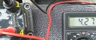
- "Secondary" requires a similar check. But now the first probe goes to the side terminal, and the second to the central terminal. In addition, the indicators will be calculated in thousands of ohms. So, in accordance with the factory figures for the VAZ 2106 it should be 5400-9200 Ohms, for 2109 and 2110 - 0.40 kOhm (coil 3122.3705) or 1.00 kOhm (coil 8352.12).
- Also check the insulation resistance to ground. To do this, install one probe on the coil body, the second on each of the terminals in turn. The tester should show at least 50 mOhm.
The ignition coil cannot be repaired
Strong deviations from the normal range are a reason to replace the coil with a new one. It should be noted that this element of the ignition system cannot be repaired.
We check the functionality of the ignition modules: injector 8 16 valves
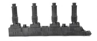
The ignition systems on carburetor and injection Ladas are very different. Thus, the “ten” was first equipped with a classic housing ignition coil, like the 2109. But then, with the start of installation of 8-valve injection engines under the hood, it became necessary to replace the old “bobbin” with a more modern ignition module. This element contains a two-channel switch and 2 coils at once, which provide a spark for two pairs of spark plugs. With the advent of the era of 16-valve engines, individual ignition coils began to be installed on Ladas - one for each spark plug. According to the rules, the ignition module must be checked on a special stand. But, as in the case of a classic coil, there is a chance to achieve the truth with the help of a tester.
A little about prices
We have already noted which switch and transistor are used when repairing the ignition module of a dozen. The first costs about 3 dollars, and for the second you will have to pay about 6 dollars.
Some craftsmen use a domestic analogue of the transistor - model KT848A . Of course, it costs less. But its problem is its lower quality and larger size, which somewhat complicates the repair process.
How to check the ignition module on a VAZ 2110 and VAZ 2114
To ensure that the ignition module on an 8-valve injection valve is working properly, you need to use a multitester in ohmmeter mode. The resistance between paired terminals should be measured.
That is, first measure the resistance of the “secondaries” between the terminals on cylinders 1 and 4, then on cylinders 2 and 3. Exact numbers can be found in the operating manuals for specific motors, but this information is not of great importance. The indicators simply should not differ from each other; an amplitude of ±100 Ohms is allowed. If the resistance in the pairs is different, the module must be replaced.
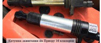
We check the serviceability of the ignition coils on a Priora with a multimeter
Unlike conventional 8-valve engines, which use an ignition module, more modern 16-valve power units come with 4 individual coils. German coils manufactured by Bosch are installed on the conveyor. Accordingly, professional equipment is provided to “treat” such parts. To do this you will need to shell out about $300, which is not cheap. However, in practice, cheap self-diagnosis is also possible.
Recommendation: before starting work with a multimeter (tester), check its accuracy. To do this, set the resistance to 200 Ohms and connect the probes to each other. Ideally, the display should show only zeros.
A car with a charged battery may not start due to a faulty ignition coil.
If not, just remember or write down this figure so that you can then subtract it from the measurement results as an error.
- Remove all coils from their seats and clean them of dirt. Check the coils for damage to the rubber elements. Nothing like this should happen - otherwise it should be replaced immediately.
- “Ring” the primary winding. To do this, connect the tester probes to pins 1 and 3 of the connector (outermost pins). Polarity doesn't matter. The resistance reading should be around 0.5 ohms. If there is a winding break, the tester will show a very large number, close to infinity.
- To measure the secondary resistance, switch the ohmmeter to the 2000 kOhm (2 mOhm) position. In this case, polarity is important: connect the red wire to the spring inside the cap, install the probe of the black wire on pin 2 (in the middle of the connector). The resistance should be about 342 kOhm.
Dear drivers, one of the reasons for poor engine starting is a burnout in the ECU of the power key gb10nb37lz.
But for some reason, many car owners immediately think that their Crankshaft Position Sensor has failed, I once had this problem. But this was also due to the fact that the wire from the sensor lay on ground and when the engine heated up, the braid melted and a short circuit occurred. In my blog: www.drive2.ru/l/6251079/
And so, our ignition diagram:
1 – battery 2 – ignition switch 3 – ignition relay 4 – spark plugs 5 – ignition module 6 – controller 7 – crankshaft position sensor 8 – master disk A – matching device
When the car does not start, most people immediately blame the crankshaft position sensor. Changing it they realize that it didn’t help. When checking the block, the wire does not give any result. The next steps are to install a new module, or this also does not give the computer anything. The car still won't start.
Everything is simple: the crankshaft sensor just has its own resistance, like the ignition module, by ringing it you can understand whether they are in good condition. Also don’t forget to check the fuse and main relay. Next, we check the spark plugs and armor wires to see if the retractor on the starter works (just put your hand on it, and if it doesn’t hit when starting, it means it’s working). During this check, you can understand what is wrong.
Checking the Crankshaft Position Sensor:
2. We quickly move the screwdriver blade close to the end of the sensor, while we observe voltage surges on the voltmeter.
Conclusion: The sensor is working.
Checking the DPKV circuit: With the ignition off, disconnect the engine management system wiring harness block from the crankshaft position sensor. We connect the tester probes to terminal “B” of the wiring harness block and engine ground.
Checking the ignition module of the injection VAZ 2110 8/16 valves
The top ten may have an eight-valve engine 2111, with a volume of one and a half liters, or an engine 21114, with a volume of 1.6 liters. The difference between them is in the ignition modules.
The module for a one and a half liter engine has the article number 2112-3705010, and the module with a volume of one thousand six hundred cubic meters has the article number 2111-3705010. They also differ in price. If the cost of the first ranges from one and a half thousand rubles to 2100, then the cost of the second is cheaper by about five hundred rubles.
Which one should you choose? The most reliable ones are produced in the city of Stary Oskol.
Module structure
It consists of two ignition coils and two high-voltage switch switches. The coils are designed to create high-voltage pulses.
In essence, it is a simple transformer that has two windings: a primary winding, with an induction voltage of approximately five hundred Volts, and a secondary winding, with an inductive voltage of at least twenty kiloVolts. Everything is placed in one housing with one connector for signal wires and four for high-voltage.
Schematic diagram of the VAZ 2110 module
The operation of the ignition module is based on the “idle spark principle”. The module is capable of distributing a spark in pairs: to the first and fourth, second and third cylinders when transmitting pulses from the electronic control unit.
Possible faults
You can ring the VAZ-2110 ignition module yourself.
The main task of the module is to supply current to the spark plugs. A high-quality spark is enough to ignite the working mixture. If there is no spark, then problems with the engine are inevitable in the form of a decrease in power, an increase in fuel consumption, dips during acceleration, the speed fluctuates, and the engine refuses to work during startup.
Symptoms and check
If one coil fails, two cylinders stop functioning. This is easy to notice, since the engine becomes heated at idle, starting is difficult, gasoline consumption increases sharply, and dynamics are lost.
We remove the connector from the VAZ 2110 module by slightly moving the latch and pulling the wire.
We check the voltage between pin 15 and the block ground.
Circuit for checking the primary windings
Secondary winding test circuit
Scheme for checking the module for short circuit
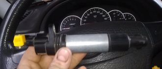
You need to make sure the spark plugs are working. They are unscrewed and the spark is checked separately on each of the spark plugs. A high-voltage wire is placed on the spark plug head. The spark plug is placed in such a way that the threaded part of the spark plug and the engine mass are in contact. If, when cranking the engine with the starter, the spark is very weak or absent altogether, then it needs to be replaced. If there is no result, you need to check the high-voltage wires. This excludes spark plugs, caps and high-voltage wires from the list of faults. This means it’s time to move on to checking the ignition module. How to do this?
First of all, the body is carefully inspected, the surface of which must be intact. If chips, cracks or burns are detected, then the module must definitely be replaced.
If spark instability is noticed only on the first and fourth, or second and third cylinders, then the conclusion arises that some coil is damaged.
Even if this is the case, due diligence needs to be done.
Checking the VAZ-2110 ignition module with a multimeter 8 valves is as follows:
- The connector with signal wires is disconnected from the module.
- It is then removed from the module. The latch must be moved to the side and pulled by the wire.
- The ignition is turned on to check the voltage at the terminal of the central block of control wires. If there is no voltage when the battery is charged, or if the value is less than the nominal value, which is twelve volts, it is concluded that the electronic control unit is faulty.
- The high-voltage wires are removed, and it is necessary to unscrew and remove the module mounting bots.
- The resistance on the primary windings of the coils is checked. The multimeter is set to resistance measurement mode. Using the device, readings are taken from the rightmost and central terminals, then the leftmost and central ones are checked. The nominal resistance should be about 0.5 ohms.
- The primary windings are checked. The resistance in the secondary windings is measured between the terminals of the first and fourth, second and third high-voltage wires. Nominal resistance 5.4 kiloohms. If a discrepancy is found, it means that the coil is not operating correctly.
- The module is checked for a short circuit. One of the tester probes is installed on the central terminal, the other on the metal body. If there is no indication of a short circuit, a conclusion is drawn that the housing of one of the coils is short-circuited.
Instructions for checking the ignition coil with a multimeter
Verification of the described element is a three-step process. It starts with careful preparation. Then a visual inspection is carried out and everything ends with testing the system using special instruments.
The functioning of the coil can be checked on professional diagnostic stands in special services and dealership centers. To do this yourself, you will need to use a multimeter. This tool is a universal diagnostic device with the widest possible range of applications.
You may also be interested in our specialist’s article on how to check a lambda probe with a multimeter.
Preparatory operations
Before you begin diagnosing the ignition coil itself, you will need to prepare a multimeter. This device is able to determine accurate voltage readings and the level of electrical resistance in Ohms.
Modern cars have different types of ignition coils. The parameters of each model are indicated by the PTS of each car. Such indicators need to be known so that diagnosis can be made. The test consists of identifying such a parameter as the resistance of the ignition coil, that is, the resistance of the secondary and primary windings. If during the verification process it is not possible to detect resistance indicators, it will be possible to rely on generally accepted signs.
Visual inspection
External system characteristics may vary slightly depending on the model. The following characteristic elements differ:
- lid;
- frame;
- centrally located terminal;
- two contacts.
During the visual inspection of the element, you will need to carefully examine the condition of the body and try to detect cracks, chips and burnt areas on the surface. Due to the fact that the housing is made of hard rubber and, accordingly, does not allow current to pass through, the malfunction of the device will mostly be associated with internal damage.
If, in the process of studying the state of the external characteristics of the coil, certain problems are identified, the element will need to be replaced with a new one. The new coil must strictly comply with all the necessary technical characteristics - winding resistance, duration and spark energy. If no problems with external characteristics are detected, you can proceed to checking the primary and secondary windings.
Checking the primary winding
At this stage, you need to connect the multimeter to the negative and positive terminals, and set the device to measure the resistance level. Despite the fact that devices from different cars are characterized by different resistance levels, the indicator fluctuates in the range of 0.4 - 2 ohms.
If during the diagnostic process the device displays a value within this range, we can judge the serviceability of the device. The display of a value of 0 Ohm directly indicates that a short circuit has occurred in the winding. If the resulting value is infinity, a break has occurred in the electrical circuit. After checking the primary winding, you can begin to detect problems with the secondary.
Checking the secondary winding
During this test, the multimeter probes will need to be connected to the positive contact and to the high voltage wires. If the device has a special plate core, the resistance parameters will be in the range of 6 - 9 kOhm. All other coil categories will exceed 15 kOhm.
Comparison of measurement results with normalized values
After checking and determining the resistance level of the two categories of windings, all the readings obtained must be compared with the standard parameters established by the manufacturer. Thoroughly checking a dual coil is a more difficult task. The primary winding in coils of this type is connected directly to the connector.
The standard double coil circuit is somewhat different from the usual one and knowledge of it is necessary in the process of checking the primary winding. The secondary winding will ring without any problems. For this purpose, it is enough to simply connect the tester to a pair of high-voltage leads.