The VAZ-2112 car was produced at AvtoVAZ from 1998 to 2009, in Ukraine from 2009 to 2014. The following are color wiring diagrams (injector and carburetor) with a description of all elements for various modifications. The information is intended for self-repair of cars. Electrical circuits are divided into several blocks for ease of viewing via a computer or smartphone; there are also circuits in the form of a single picture with a description of the elements - for printing on a printer in one sheet.
To diagnose and repair yourself, first look to see if everything is okay with the generator. Is it put on well and does not sag? This procedure must be done with all versions of the fuel system, both carburetor and injection. We check the fuses according to the electrical diagram. The reverse side of the safety block cover will also be of great help. There are clues there that the diagram will help you decipher. Replace the burnt out element and try to start the car again. You need to check whether the battery terminals are tightly connected and whether they are oxidized. Is the wire going from the battery to the generator and to the starter damaged?
Modifications of the VAZ-2112 car
VAZ-21120 . Modification with a 16-valve injection engine with a volume of 1.5 liters and a power of 93 horsepower. 14-inch wheels were installed on the car. This modification has a problem with valves bending when the timing belt breaks. The problem can be solved by increasing the depth of the grooves in the piston bottoms.
VAZ-21121 . The car was equipped with a VAZ-21114 8-valve injection engine with a volume of 1.6 liters and a power of 81 horsepower.
VAZ-21122 . Budget modification with an 8-valve injection engine VAZ-2111. The car was produced without electric windows, the wheels were 13 inches in size, and the brakes were unventilated from a VAZ-2108 car.
VAZ-21123 Coupe . Three-door, five-seater hatchback. The only two doors for entering the car are 200 millimeters wider than those of the five-door hatchback, and they are mounted on new, durable hinges. The rear arches of the car have become wider. The engine was installed with a 16-valve injection engine with a volume of 1.6 liters and a power of 90 horsepower. The car was produced from 2002 to 2006 in small quantities, the reason for this was the high cost of the car.
VAZ-21124 . Modification with a 16-valve injection engine VAZ-21124 with a volume of 1.6 liters. Produced from 2004 to 2008. For this type of engine, the problem with valve bending was solved. To do this, the depth of the grooves in the piston heads was increased (up to 6.5 mm). In addition, the design of the cylinder block was changed to achieve a working volume of 1.6 liters, for which its height was increased by 2.3 mm, and the radius of the crankshaft was increased by 2.3 mm accordingly. There were also a number of other minor changes.
VAZ-21128 . The luxury version of the car, produced by Super-auto JSC, was equipped with a 16-valve VAZ-21128 engine with a volume of 1.8 liters and a power of 105 horsepower.
VAZ-2112-37 . A racing modification of the VAZ-2112, prepared for the “ring” in the Lada Cup qualifying group. The car was equipped with a 1.5-liter VAZ-2112 engine with a power of 100 horsepower. The racing car was equipped with a safety cage, an external aerodynamic kit and a front extension of the strut support cups.
VAZ-2112-90 Tarzan . All-wheel drive modification with a VAZ-2112 body on a frame chassis with transmission and suspension parts from a VAZ-21213 Niva. It was also equipped with a 1.7 or 1.8 liter engine from the Niva.
How to repair the fuel pump on a VAZ 2110-VAZ 2112?
Note! Before you say unequivocally in such a matter that the pump specifically has become unusable, you should check if your fuel filter is dirty and it’s not even the pump but the filter itself that needs replacement. As it is also called, due to dirty injectors, by and large the same symptoms as As a rule, there are, because in order to be more likely to blame the pump, first check the pressure in the power system and thanks to this check it will not be difficult to identify the malfunction! (You can learn how to check the pressure in the text of the article, which is called: “Checking the pressure in the fuel rail on a VAZ”
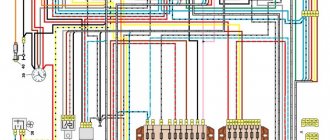
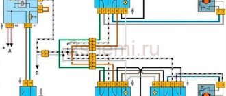
Electrical diagram of VAZ-2112
Designations: 1 – Headlight, 2 – Klaxon, 3 – Main radiator fan, 4 – Starter, 5 – Battery, 6 – Generator 2112, 7 – Gearbox limit switch (reverse), 8 – Actuator in the front passenger door, 9 – Power window enable relay, 10 – Starter relay, 11 – Heater fan, 12 – Electric heater partition drive, 13 – Main pump, 14 – Washer reservoir sensor, 15 – Driver’s door actuator, 16 – Front passenger window selector, 17 – Unlock button fifth door, 18 – Heater fan resistance unit, 19 – Main wiper motor, 20 – Driver’s window lift selector, 21 – Front passenger’s window lift motor, 22 – Central locking, 23 – Exterior light switch, 24 – Brake fluid leakage sensor, 25 – Pump additional, 26 – Driver's window lift motor, 27 – PTF on indicator, 28 – PTF switch, 29 – Dashboard, 30 – Heated glass on indicator, 31 – Heated glass switch, 32 – Steering column selector switch, 33 – PTF relay, 34 – Ignition switch, 35 – Main fuse block, 36 – Illumination of heater controls, 37 – Hazard warning button, 38 – Heater control controller, 39 – Glove compartment lighting, 40 – Glove compartment lid end cap, 41 – Cigarette lighter, 42 – BSK – display unit, 43 – Ashtray illumination, 44 – 12V socket, 45 – Instrument lighting switch, 46 – Actuator in the right rear door, 47 – Right rear passenger window selector, 48 – Clock, 49 – Right rear passenger window motor, 50 – Brake limit switch (closed – pedal is pressed), 51 – Left rear passenger window motor, 52 – Left rear passenger window selector, 53 – Actuator in the left rear door, 54 – Turn signal, 55 – Handbrake limit switch (closed – handbrake on), 56 – Rear wiper motor , 57 – Navigator's lamp, 58 – Interior lamp, 59 – Temperature sensor in the heater, 60 – Limit switch for the open front door, 61 – Limit switch for the open rear door, 62 – Trunk light, 63 – Rear optics (on the body), 64 – Rear optics (on the fifth door), 65 – License plate illumination.
The letters indicate the terminals to which it is connected: A – Front speaker on the right, B – Radio, C – Injector harness, D – ESD diagnostic connector, D – Front left speaker, E – Diagnostic connector for the heater controller, G – Rear right speaker, W – Rear left speaker, I – BC connector, K – glass heater thread, L – fifth door actuator, M – Additional brake light.
Wiring diagram VAZ-2112 injector 16 valves - full view
VAZ-21124 engine control circuit
Connection diagram of the VAZ-21124 engine control system with distributed fuel injection to Euro-2 emission standards (controller M7.9.7): 1 - ignition coils; 2 — nozzles; 3 - controller; 4 - main relay; 5 - fuse connected to the main relay; 6 — cooling system electric fan relay; 7 - fuse connected to the cooling system electric fan relay; 8 - electric fuel pump relay; 9 - fuse connected to the electric fuel pump relay; 10 — mass flow and air temperature sensor; 11 — throttle position sensor; 12 — coolant temperature sensor; 13 — solenoid valve for purge of the adsorber; 14 — oxygen sensor; 15 — knock sensor; 16 — crankshaft position sensor; 17 — idle speed regulator; 18 — immobilizer control unit; 19 — immobilizer status indicator; 20 - phase sensor; 21 — vehicle speed sensor; 22 — electric fuel pump module with fuel level sensor; 23 — oil pressure warning lamp sensor; 24 — coolant temperature indicator sensor; A - block connected to the wiring harness of the ABS cabin group; B — diagnostic block; B - block connected to the air conditioner wiring harness; G - to the “+” terminal of the battery; D — to the side door wiring harness block; E - block connected to the instrument panel wiring harness; G1, G2 - grounding points; I - the order of conditional numbering of plugs in the block of the immobilizer control unit; II - the order of conditional numbering of contacts in the diagnostic block.
Useful: VAZ 2110 diagram
Connection diagram of the VAZ-21124 engine control system with distributed fuel injection under Euro-3 toxicity standards (controller M7.9.7): 1 - ignition coils; 2 — nozzles; 3 - controller; 4 - main relay; 5 - fuse connected to the main relay; 6 — cooling system electric fan relay; 7 - fuse connected to the cooling system electric fan relay; 8 - electric fuel pump relay; 9 - fuse connected to the electric fuel pump relay; 10 — mass flow and air temperature sensor; 11 — rough road sensor; 12 — throttle position sensor; 13 — coolant temperature sensor; 14 — idle speed regulator; 15 — control oxygen sensor; 16 — diagnostic oxygen sensor; 17 — solenoid valve for purge of the adsorber; 18 — knock sensor; 19 — crankshaft position sensor; 20 — immobilizer control unit; 21 — immobilizer status indicator; 22 - phase sensor; 23 — vehicle speed sensor; 24 — electric fuel pump module with fuel level sensor; 25 — oil pressure warning lamp sensor; 26 — coolant temperature indicator sensor; A - block connected to the wiring harness of the ABS cabin group; B — diagnostic block; B - block connected to the air conditioner wiring harness; G - to the “+” terminal of the battery; D — to the side door wiring harness block; E - block connected to the instrument panel wiring harness; G1, G2 - grounding points; I - the order of conditional numbering of plugs in the block of the immobilizer control unit; II - the order of conditional numbering of contacts in the diagnostic block.
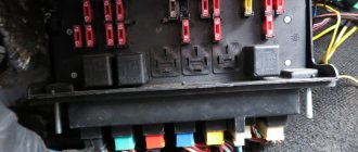
Replacing the fuse box of a VAZ 2110.
As for the direct replacement of the latter, it is by monitoring the serviceability of the latter that it is necessary to begin diagnosing the failed element of the electrical circuit. The fuse is removed with tweezers or, if the thickness of the fingers allows, simply by hand from the landing block and inspected in the light to see if the fusible conductor is closed. In the event of combustion, a new fuse of the appropriate rating must be installed in place of the failed one in the fuse box.
Replacement video
In conclusion, I would like to note that the creators of the VAZ 2110 actually did not limit themselves to just this fuse box; in fact, there is another place, more hidden from prying eyes and the driver - under the decorative panel, to the left of the center console pillar at the passenger’s feet.
There are three fuses located here: the ignition module, the fuel pump and the sensor assembly (speed, oxygen, air flow and absorber purge). In addition, there are three relays: ignition relay, fuel pump relay, electric fan relay.
So, when looking for the cause of your car breakdown, do not forget about them. Read about the VAZ 2109 fuse box here.
VAZ-2112 harness diagrams
Instrument panel harness diagram
1, 2, 3, 4 – instrument panel harness pads to the front harness; 5 — block of the instrument panel harness to the side door harness; 6, 7, 8 — instrument panel harness pads to the rear harness; 9 – rear window heating switch; 10 – light signaling switch; 11 – windshield wiper switch; 12 – block of the instrument panel harness to the radio; 13 – mounting block; 14 — instrument cluster; 15 – heater control controller; 16 – heater motor switch; 17 — block of the instrument panel harness to the ignition system harness; 18, 19 — blocks of the instrument panel harness to the air supply box harness; 20 — ignition switch; 21 – fog lamp relay; 22 – sound signal relay; 23 — power window relay; 24 — starter relay; 25 – seat heating relay; 26 – external lighting switch; 27 – fog lamp switch; 28 – cigarette lighter; 29 – lampshade lighting of the glove box; 30 – glove box lighting switch; 31 – switch for rear fog lights; 32 – right steering column switch; 33 – socket for connecting a portable lamp; 34 — instrument lighting switch; 35 – brake signal switch; 36 – sound signal switch; 37 – alarm switch; 38 – air distribution drive gearmotor; 39 – VAZ-2112 illuminator; 40 — instrument panel harness block to the front harness; 41 – trunk lock drive switch; 42 – rear fog light relay.
A – grounding point of the instrument panel harness.
Front 2112 harness diagram
Air supply box wiring diagram
VAZ-2112 heater harness diagram
Side door harness diagram
Luxury side door harness diagram
Rear Harness Diagram 2112
- common terminal block of the wiring harness for connecting the wiring coming from the instrument panel (in the diagram under No. 1);
- terminal block of the wiring harness for connection with the wiring of the instrument panel of cars in the “standard” configuration and for connection to the side door harness for cars in the “luxury” configuration (in diagram No. 2);
- rear harness terminal block for connection to the instrument panel harness (No. 3);
- two 4-pin terminal blocks (for modifications 2112-3724558-10 16 valves). Indicated on the diagram as No. 4 and No. 5;
- side direction indicators (no. 6 – left, no. 7 – right);
- power supply to the individual lighting lamp (number 8 on the diagram);
- power supply for the general interior lighting lamp (No. 9);
- handbrake sensor connector (No. 11);
- rear lights (in the diagram No. 11 is left, No. 12 is right);
- interior temperature sensor connector (No. 13 in the diagram);
- connector for connecting 4 interior dome light switches (in the diagram under numbers 14,15,16 and 17);
- connector for trunk light (No. 18);
- reserve block of the wiring harness (in diagram No. 19). Can be used as a connector to connect to the side door wiring harness;
- block for connecting the wiring harness of the license plate lights (no. 20 in the diagram);
- The wiring grounding points are indicated in the diagram as A and A1.
For the lights, tailgate and license plate lights. They are connected together and the light harness is connected to the instrument panel harness and any side door harness, from it to any additional harness (will be below) with the trunk release button. The connector with the gray wire of the light harness is connected to the instrument panel; on luxury versions, it is connected to the instrument panel through the luxury side door harness (heated mirrors are connected to it).
VAZ2112 fuses and relays
- F1 5 License plate lamps. Instrument lighting lamps. Side light indicator lamp. Trunk light. Left side marker lamps
- F2 7.5 Left headlight (low beam)
- F3 10 Left headlight (high beam)
- F4 10 Right fog lamp
- F5 30 Electric door window motors
- F6 15 Portable lamp
- F7 20 Electric motor of the engine cooling system fan. Sound signal
- F8 20 Rear window heating element. Relay (contacts) for turning on the heated rear window
- F9 20 Recirculation valve. Windshield and headlight cleaners and washers. Relay (coil) for turning on the rear window heating
- F10 20 Reserve
- F11 5 Right side marker lamps
- F12 7.5 Right headlight (low beam)
- F13 10 Right headlight (high beam). High beam warning lamp
- F14 10 Left fog lamp
- F15 20 Electric seat heating. Trunk lock lock
- F16 10 Relay-breaker for direction indicators and hazard warning lights (in emergency mode). Hazard warning lamp
- F17 7.5 Interior lighting lamp. Individual backlight lamp. Ignition switch illumination lamp. Brake light bulbs. Clock (or trip computer)
- F18 25 Glove box lighting lamp. Heater controller. Cigarette lighter
- F19 10 Door locking. Relay for monitoring the health of brake light lamps and side lights. Direction indicators with warning lamps. Reversing lamps. Generator excitation winding. On-board control system display unit. Instrument cluster. Clock (or trip computer)
- F20 7.5 Rear fog lamps VAZ-2112.
- K1 – lamp health monitoring relay;
- K2 – windshield wiper relay;
- K3 – relay-interrupter for direction indicators and hazard warning lights;
- K4 – headlight low beam relay;
- K5 – headlight high beam relay;
- K6 – additional relay;
- K7 – relay for turning on the heated rear window;
- K8 – backup car relay.
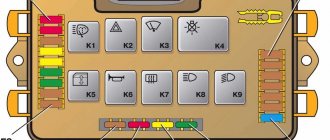
Fuse connection diagram
The figure below shows the order of connecting the plugs in the mounting block.
Drawing of connecting the plugs to the corresponding blocks of the mounting block.
The figure below shows a complete diagram with mounting block symbols.
From this diagram it is not difficult to figure out the order in which the plugs are connected.
Relay value:
- K1 - serviceability of lamps,
- K2 - windshield cleaner,
- K3 - turn signals, emergency lights,
- K4 - low beam,
- K5 - high beam,
- K6 - additional relay,
- K7 - heated rear window,
- K8 is an unused relay on VAZ models of the tenth family.
Video on removing the unit and replacing fuses
Main settings
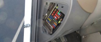
The fuse box is located under the decorative panel to the left of the steering column. Removing it is quite simple: press the latch and lower the structure down. Once you have access to the fuses, they can be removed and checked for integrity using a millimeter. The block contains only 20 fuses, designed for different current strengths.
Just look at the color of the fuse to determine what amperage it is designed for:
- tan runs at 5 amps;
- darker brown – at 7.5;
- red – at current strength 10;
- saturated blue – at 15;
- bright yellow is for 20;
- colorless or transparent – by 25;
- green – by 30.
Remember that you cannot install a stronger fuse element, and you should also not swap fuses. If the current strength is not observed, the protected unit may fail. If you do not have the necessary knowledge, entrust work with the electrical part of the board to a professional. To protect yourself from a car fire, do not install a wire in place of a failed fuse, as this will lead to a short circuit.
Behind the main unit you can notice separately connected devices, one of them protects the fog lights, and the second protects the central locking. Older cars do not have additional fuses protecting the car radio and alarm system.
If you equip your car with additional equipment, be sure to include these items.
↑ Location of fuse box
For ease of maintenance, the designers of the VAZ 2110 determined that the device was located under the steering column. The button that opens the VAZ-2110 special panel is located below the headlight control knob. Below the headlight auto-corrector button is a button that opens access to a special panel, behind which the main unit is located.
The left side of the console in the dashboard serves to accommodate an additional unit. Access to it is closed with a plastic cover. The central locking fuse is located separately, hidden in the niche of the mounting block. You can find it behind the fuse box in a plastic box. In the first modifications of the VAZ-2110, the fog lamp fuse was located behind the block and was not provided with a fastening. Its free state was maintained by a bundle of wires. After a while, the developers located it among the other fuses.
What fuses are included in the block?
In total, the block contains 20 elements. The number scheme looks like this:
- F1 protects the power circuit of the license plate lighting lamps, instruments, trunk and left side dimensions, as well as the control light indicating the operation of the side dimensions;
- F2 is responsible for the low beam of the left headlights;
- F3 – for high beam headlights on the left side;
- F4 works in conjunction with the right fog lamp;
- F5 protects electric window motors from overload;
- F6 is in the portable lamp circuit;
- F7 is responsible for protecting the horn and the cooling system fan of the power unit;
- F8 – for relay contacts and elements of the rear window heating system;
- F9 – for the relay coil for turning on the heated rear window, recirculation valve, windshield and headlight washers, as well as for their cleaners;
- F10 is in reserve;
- F11 protects the chain of dimensions located on the right;
- F12 is responsible for the functionality of the low beam of the right headlights;
- F13 – for the functionality of the high beam headlights on the right and the indicator light notifying that this type of lighting is turned on;
- F14 is in the circuit with the left fog lamp;
- F15 protects the luggage compartment lock and heated seats;
- F16 works with hazard warning lamps and turn signal breaker relay;
- F17 is responsible for the brake light and interior lighting lamps located near the clock or on-board computer screen, at the ignition switch, in the individual lighting circuit and on the ceiling;
- F18 – for glove compartment lighting, cigarette lighter and heater controller;
- F19 - for the control relay of the stop signal and side lights, locking, turn indicator lamps, on-board control system indication, clock or computer, generator winding and instrument cluster.
- F20 – for rear fog lights.
The rated current is determined by the color of the fuse. As you can see, most elements are part of a chain of several nodes.
Electromagnetic relays
To relieve the car switch contacts from high current consumption, electromagnetic relays are used in the electrical circuit. There are 8 of them in total:
- K1 is responsible for the serviceability of the lamps;
- for turning on the front window wiper - K2;
- for turn signals and hazard warning lights – K3;
- for low beam headlights - K4;
- for turning on the high beam - K5;
- for heating the rear window - K7;
- for fog lights located at the rear - K8.
The block contains relay K6, which is additional. Before installing a new element into the system, check the wiring for short circuits, otherwise the parting that is protected by the fuse element or the fuse itself may fail. The described block is the main one, but the only one in the VAZ-2112 electrical circuit.
Sources
- ladaautos.ru/vaz-2112/raspinovka-bloka-predoxranitelej-vaz-2112-inzhektor-16-klapanov.html
- 2shemi.ru/shema-vaz-2112/
- vazdriver.ru/blok_predohraniteley_vaz2110/shema_i_raspolozhenie_predohraniteley_vaz_2110_2111_2112.html
- drive2.ru/l/2251582/
Electrical diagram of the safety block VAZ 2110 (2112)
Each protective element has its own position on the block set by the designer, so finding it should not be difficult. You don't need to understand the intricacies of electrical wiring. To check the operation of fuses and relays, it is enough to know which one is responsible for what.
Please note that opposite each protective element in the block its rating and the graphic designation of the powered electrical receiver are stamped. Thus, on the VAZ 2110 the fuse block diagram is not really needed, because all the issues can be sorted out locally.
If you are not particularly used to understanding graphic symbols, or for some reason you don’t have them, this is also not a problem
The mounting location of each individual component in the block is far from a secret, as is its purpose. More information about why this or that fuse is needed on the VAZ-2110 can be found in the operating instructions or in the attached illustration.
If you are not particularly used to understanding graphic symbols, or for some reason you don’t have them, this is also not a problem. The mounting location of each individual component in the block is far from a secret, as is its purpose. More information about why this or that fuse is needed on the VAZ-2110 can be found in the operating instructions or in the attached illustration.
What is important to know when repairing the fuse box on a VAZ 2110 (2112)
Replacing a particular fuse is a simple thing and only requires taking into account its rating. There are no other parameters. If you are changing a VAZ-2110 relay, you should take into account not only its design parameters, but also its electrical parameters: the operating voltage, markings and location of the executive contacts must match.
If a newly installed fuse immediately blows, there is a short circuit in the electrical wiring and a sharp excess of normal current in the electrical circuit. If the protection does not burn out immediately, but with enviable regularity, either you have chosen the wrong rating, or an overload occurs in the electrical circuit. The condition of the actuator powered by the fuse should be checked.
Sources
- https://luxvaz.ru/vaz-2110/253-shema-predohraniteley.html
- https://avtozam.com/vaz/2110/zamena-predohranitelej-svoimi-rukami/
- https://vashalada.ru/mashiny/vaz-2110/zamena-bloka-predoxranitelej-vaz-2110.html