Connecting the central lock
First you need to study in detail the connection diagram for the central locking on a VAZ car - 2115,2114. Finding it is not a problem by searching on the Internet.
The central locking control module is located on the left under the dashboard. Looking there, you will find six wires coming out of the module housing. To install the alarm, you must disconnect the blue and brown cords. As a result, we get a connection corresponding to the following diagram:
Before connecting the alarm, you should make sure that it is not a toggle switch installed on the driver's door, but a standard actuator with five outputs. Otherwise, you will need to install an actuator, which is quite problematic.
On VAZ -2115,2114 cars, the white wire, which is connected to the seventh terminal, is usually responsible for unlocking. If there are no connections at terminals 7 and 5, then the eighth terminal is connected to the brown cord. It is this cord that is responsible for unlocking in this case.
Terminals number five and six are responsible for locking the lock. This arrangement of contacts is typical for almost all blocks of the “ninth” series.
For some reason, none of the instructions for alarms ever indicate that installation requires the purchase of additional elements.
We will definitely need:
- Two to three 1N4001 diodes per Ampere
- One 1N5401 3 Ampere diode
- Two 4 or 5 Ampere diodes if there are no separate outputs for turn signals.
When installing a Starline alarm system, the task is greatly simplified, since significantly fewer additional parts are needed.
How the central lock works
The operation algorithm of the central locking system consists of sending a pulse to the VAZ 2114, in which the received signal is analyzed and commands are generated that control the door locks. They are either opened or locked.
General scheme of central locking
Elements that activate the central locking are connected to pin 30. If contact 87 closes, then the activator outputs will be affected by ground. When a certain relay 30 is activated, the contact will connect to the positive. Thus, the activator will receive power and the rod will begin to move. The control unit rod closes different pairs of signals depending on what action needs to be performed: closing or opening the doors.
Since the central locking activators are connected in parallel, all doors will either open or lock at the same time. Central locking can be pneumatic or electric. The first type of device includes a control panel, compressor and tubes. In an electric one, the main element is a motor, thanks to which the mechanisms are activated.
Connection diagram
After carefully studying the alarm installation instructions, you can find the following connection diagram:
In this diagram, the designation X2 indicates a six-pin connector. It must be connected according to the diagram above. If you need to install an additional actuator, then it is better to use the diagram given in the instructions.
Now let's figure out how to connect the door sensors. For this purpose, there is a special wire in the connector marked X3.
Tapping into wires
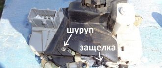
Next to the driver's door, there are two wire harnesses running right along the floor. One of them has a cable coming from the parking brake and two wires to the turn signals. The second harness contains the door switch cable. This is where you need to start connecting. To do this, remove the sill trim along with the side panel. They are attached using self-tapping screws that must be unscrewed. Having done this, you can see the wiring harness shown in the photo:
This harness goes to the dashboard. We are interested in the door switch cable. If a 1N5401 diode is inserted into the wire break, the current should flow towards the limit switches. And the second diode 1N4001 is connected as shown in the figure.
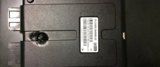
The following figure shows the second harness:
At the same time, taps are made from the blue cables and the cords are pulled to the place where the alarm will be installed. And the handbrake wire is cut, and a 1N4001 diode is soldered into the cut with the cathode towards the switch.
Connecting autorun
The VAZ-2114 models use an ignition switch with three terminals - 15 (blue wire), 30 (lilac) and 50 (red). Terminal 30 is connected to the battery. When you turn the key, blue wire 15 is connected to this terminal. The third terminal is responsible for the starter.
As it is written in the instructions, it is quite possible to power the alarm from contact 30, from which the lead is made. And the cable from connector X1, yellow, is connected to connector 15.
After all the actions taken, the connection of the tachometer remains. In this case, a loop antenna and a reading device are combined. Connector X3 has a gray-black outgoing wire. It is connected to the tachometer as shown in the VAZ dashboard diagram:
This will allow the alarm to control the speed. And at the very end we connect the ground from the main unit. This is a black cord from connector X3.
Settings
Only autorun functions can be configured. To activate programming mode:
- Disable security
- The ignition key is set to position 0.
- Then press the Valet key six times in the main block.
- Turn on the ignition
- After six beeps, use the same key to select the desired function, and use the key on the key fob to select the desired value.
The optimal settings for VAZ - 2115.2114 will be the following: function 12 - set to value 3, function 11 - value 4, function 9 - value 3. To select value 4, press and hold the third button until the melody is played.
After playing, press it again. To check the correct connections, perform the following steps:
- Disconnect the yellow cord from block A91 to terminal 15 for a while.
- The engine is started using the ignition key
At the same time, the alarm indicator should blink.
Subscribe so you don't miss anything important
The central locking VAZ 2114 (hereinafter referred to as CZ) is a mechanism that ensures the simultaneous closing or opening of all four doors in the car. This option is very convenient; it eliminates the need to reach out and lock the doors manually every time. Such centralized control comes in handy when installing car alarm systems, which significantly expands the possibilities and variations of the use of the locking mechanism.
Content
Installation instructions for central locking
Before installing the central locking system, you should study the connection diagram
Photo gallery “Central locking diagrams”
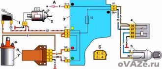
1. Central locking diagram for VAZ 2114
2. Central locking diagram
3. Connection diagram of the central locking system to the alarm system
The central locking control module is located on the left side under the panel. There are 6 wires coming from it. To install the central locking system, you need to disconnect the brown and blue wires.
Before connecting, you need to check that activators with 5 outputs are installed in the doors. If they are missing, they should be installed.
In a car, the one responsible for opening the doors is usually white and connected to terminal 7. If there is no connection to terminals 7 - 5, then the 8th terminal is connected to the brown wire. This wire is responsible for opening the doors. Terminals 5 and 6 are for closing doors.
To install the central locking system, you must purchase additional items:
- 2-3 diodes 1N4001 at 1A;
- one diode 1N5401 3 A;
- 2 diodes of 4 or 5 A, if there are no separate outputs for turn signals.
The central locking VAZ 2114 (hereinafter referred to as CZ) is a mechanism that ensures the simultaneous closing or opening of all four doors in the car. This option is very convenient; it eliminates the need to reach out and lock the doors manually every time. Such centralized control comes in handy when installing car alarm systems, which significantly expands the possibilities and variations of the use of the locking mechanism.
The operation of the lock itself does not depend on whether the car engine is running or the fact that the ignition is turned on. Power is supplied directly from the battery. It is quite common for the system to malfunction. For example, when the locks of some doors close, but the rest do not. Or the closing process occurs with great difficulty, jamming, or partial failure of the latches. A situation familiar to many car enthusiasts, isn’t it? There are several reasons for the node to not work correctly; we will look at them in more detail.
Central locking diagram for VAZ 2114
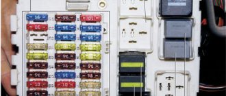
The system consists of the following components:
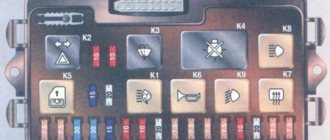
- mounting block;
- 8 amp fuse;
- 4 gearmotors (one in each door, and the one in the driver's door has a contact group);
- central locking control unit;
- wires (red, black, blue, yellow) and plugs;
- rods that are located in each door;
- limit switches that signal the current state of the door (open or closed).
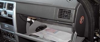
Where is the central locking of the VAZ 2114
The central locking system is located in the driver's door, just like the electric drive. If we talk about the system as a whole, it is distributed over 4 doors (in some cases it also extends to the trunk), and the central panel (control unit).
Testing and diagnostics
conclusions
In this article, we touched upon only some of the most common problems associated with the operation, repair and maintenance of a centralized lock. Despite the fact that the node has plenty of problems, restoring its functionality is not a difficult, much less an impossible task. Usually, to achieve smooth, efficient operation of the system, only practical skills are missing. After receiving them, you will be able to repair any complexity! If you want to install the central locking on a VAZ 2114 yourself, then here is a video instruction:
Content
In order to protect your car from theft, you can equip it with a device such as a central electronic lock. To do this, it is not at all necessary to contact a service or specialized workshop, because in fact, its installation is much simpler than it seems at first glance. In today's article we will talk about how to install central locking on a VAZ 2114 and how to avoid possible mistakes.
Alarm system with central locking VAZ 2114
How the central lock works
Central locking is a system that, when given a certain command, performs the function of opening or closing an object. For ease of use, this operation is performed remotely. Some car enthusiasts choose the function of closing all doors after a certain period of time. It is very convenient for those cases when the driver does not have time or forgets to close the car door. As a rule, using a long-range remote control you can control both the trunk and the hood, close and open the windows. The most common way to control the remote control is by pressing one button, after which all the locks on the car are activated. If the remote control does not work for some reason, then you need to insert the key into the door lock and turn it clockwise. If an accident occurs, the car's security system is activated automatically and all locks open. At the heart of the central locking mechanism are incoming sensors located in the structure itself. These are microswitches and door switches (limit switches), actuators and a control unit. The limit switch must maintain the door position and this information must be transmitted to the control unit. The switches fix the structural part of the door lock. The front doors of the car are equipped with a cam device. To fix the cam, the front doors are equipped with microswitches: there are two parts for each mechanism. Blocking the lock is formed by one switch, and unlocking is formed by the second. There are two more microswitches used by the central locking mechanism. A fifth switch is installed on the lever device in the lock drive. It serves to determine the door position: when the door is open, the switch contacts close and the central locking system is deactivated. The electronic mechanism (unit) receives the signal from the microswitches and sends information to the central control. In order to open an object, the central device sends a signal to certain control units, thereby activating the mechanisms in the locks.
Lock connection diagram
In order to be able to install central locking on VAZ cars, the manufacturer equipped them with a special BUBD control module. You can find it directly under the torpedo, on its left side. If this module is missing, it will simply not be possible to install the device, so before you buy an electronic lock, you should first find out whether the module is installed on the car.
Control module
The connectors of this module are equipped with 6 wires of different colors as standard. If you are installing an alarm system on a VAZ 2114, you will need to turn off brown and blue in order to get the following connection diagram:
Before you begin installing the lock, you should make sure that five-wire actuators are installed in the car doors. If it turns out that ordinary switches are installed instead of them, then it will not be possible to connect the alarm.
Another important point to remember is the need to purchase additional electronic components that are not included in the alarm kit.
These include:
- diodes 1N4001 for 1 Ampere - 3 pieces;
- three-amp diode 1N5401;
- any diode rated for a current of up to 5 Amps (only if there are no separate outputs for turn signals).
Diode wiring
Once these components have been purchased, you can begin connecting the alarm. To do this, you should carefully study the drawing with the connection plan included in the instructions (this diagram of the VAZ 2114 central lock is duplicated below) and carry out the entire installation procedure in accordance with it. So, in the diagram, the index X2 indicates the six-pin control connector (BUBD), which was mentioned at the beginning. This is where you should start connecting, guided by the same “native” circuit.
After the lock is connected, all that remains is to insert into the wires in order to connect the alarm to the door sensors.
Connecting door limit switches VAZ 2114
It is done in the following order:
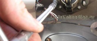
- Remove the sill trim along with the side panel by unscrewing their fastening screws.
- In the exposed wiring harness, find the cable going to the door limit switches (it has a white and black color) and solder a 1N5401 diode into its gap so that the direction of possible current flow is only towards the limit switches.
- In the second wiring harness, find two blue cables, from which you should make taps (using a wire of the same cross-section) and stretch them to the location where the alarm is attached.
- Cut the handbrake wire and solder a 1N4001 diode into its gap with the cathode towards the limit switch.
Tapping into wires
If necessary, you can make an insertion into the wires even before connecting the alarm to the connectors - this will not affect the functionality of the electronic equipment in any way.
The next step is to connect autorun. To do this, you will need to power the alarm to terminal 30 of the ignition switch, and connect the yellow cable coming from connector X1 to its 15th connector (according to the connection diagram).
After the alarm is connected to the on-board power supply, you will need to connect it to the speed sensor by connecting the gray-black wire coming from connector X3 to the tachometer. After this, all that remains is to connect the black wire X3 to the ground connector in the main unit.
At this point, the installation of the central lock can be considered complete.
Why the VAZ central locking does not work reasons
As we know, any equipment fails sooner or later.
And the central locking on the VAZ 2110 is no exception. There are a number of problems that manifest themselves in the operation of this system. Many motorists inadvertently destroy their car's security system. The driver should not give a long or rapid impulse when requesting a door to be opened or closed. Central locking diagram for VAZ
This action can damage the activator with which the closing device operates. When a long pulse is applied, the collector of the activator electric motor heats up very much. In this regard, the brush holder begins to melt and it may jam. After this, the activator will need to be replaced.
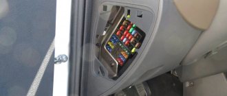
A fuse protects the central locking circuit. It is from this point that they begin to search for faults in the operation of the entire circuit. It is located inside the car, behind the fuse box. According to the diagram, it is located at the break of the pink wire (in insulation). Under the driver's mat there is a wire with a plug connector, which accumulates moisture and oxidizes. The power supply to the activator is lost. The modular central locking unit may break. You should check its functionality by applying voltage from the battery to the module connector contact. The gear activator gears are made of plastic. Such parts are subject to wear and tear and this is a mechanical failure. But the solenoid is considered the weakest point of the central lock; most often it is the one that fails. The electromagnet is controlled via a switch. When opening and closing doors, the life of the solenoids is calculated for approximately 10 thousand operations. After this number of switchings, malfunctions begin. The repair is simple: you need to replace the solenoid itself.
Settings
After the alarm system on the VAZ 2114 is fully connected, its final configuration should be performed.
It is carried out as follows:
- Disable security.
- Set the ignition key in the lock to o.
- Press the button labeled Valet 6 times in a row.
- After the step marked “3”, immediately turn on the ignition (6 beeps should sound).
- Using the Valet button, select the required function (their list is given in the table below). To set it to the required value, press the corresponding key on the alarm key fob.
In this case, the most optimal (recommended) settings will be the following:
- for function 12 - value 3;
- for function 11 - value 4;
- for function 9 - value 3.
You can check whether the alarm is connected and configured correctly as follows:
- Disconnect the yellow cord coming out of block A91 from terminal 15 of the ignition switch.
- Turn the ignition key and start the engine.
- Pay attention to the alarm LED - if connected correctly, it should blink continuously.
The last thing I would like to talk about today is the importance of correctly connecting the tachometer, which directly affects the operation of the autostart.
To avoid errors, it is recommended to make this connection strictly in the following order:
- connect the red wire from the BUBD connector to the positive 12 volt terminal;
- connect the black wire of the 18-pin connector to the vehicle ground;
- Connect the gray-black wire of the same connector to the wire coming from the tachometer.
If you then turn on the ignition, then if the tachometer is connected correctly, the alarm indicator will begin to blink evenly.
Useful video
You can glean additional useful information from the video below:
Published July 05, 2019
How to quickly, easily and most importantly correctly disable the immobilizer on a VAZ 2115?
All modern cars, including cars from the domestic automobile industry, are equipped with immobilizers. Immo. This is an anti-theft device that allows you to block the engine in the event of a car breakdown. But like any other electronic device, over time this device may malfunction or cause problems, in which case car owners will have to turn it off. How to disable the immobilizer on a VAZ 2115 with your own hands, we will talk about this below.
general information
Firstly, it will be useful to know where immo is located, because if this device is not working, you need to get physical access to the device to disable it. In VAZ 2115 cars, immo is located behind the center console to the right of the steering wheel.
Today there are two types of contact and non-contact devices. Contact systems are operated by keys, and special circuits built into the key chain or card are used to operate contactless ones. As for VAZ cars, immo is installed only on injection versions of the car.
How does it work
The operating principle of this device is based on communication between the control unit and immo. The anti-theft device transmits data to enable or disable the starting power supply. If disabled, the system automatically blocks the ignition circuit via the fuel pump and therefore the engine will not be able to start. That is, without initializing the power supply it does not work
READ Vw Passat B6 Which Engine to Choose
When should I disconnect?
In what cases do you need to disable the installation of the anti-theft system:
- If you are dealing with manufacturing defects, this is a disadvantage. Especially, this applies to the earliest versions of vehicles on which such devices were installed. In later versions, VAZ engineers added an alternative engine starting function, bypassing the protection. But you must keep in mind that in this case the parameter will only work once, if a failure occurs, you need to enter the access code, then activate the function and press the gas pedal a certain number of times.
Moreover, this operation will need to be repeated 6 times. For example, if your password is 123897, you first press the pedal once, then twice (after a short period of time), then three more times, then eight times, etc. This function is described in more detail in the service brochure.
If the battery is completely discharged, the control unit may correct this as an error that will prevent the engine from starting in the future. As mentioned above, the immobilizer control module communicates with each other through a diagnostic line. Therefore, if power is lost in the circuit, there is an error. The lock can also be connected to the control unit. For example, if a driver uses diagnostic equipment to check vehicle systems, a code failure may occur. In this case, inflammation must be turned on. In addition, interference caused by a smartphone can also cause a failure. Also, the need to bypass immo may be associated with banal malfunctions in its operation (author of the video channel IZO))) LENTA).READ How much oil to fill in a VAZ 2115 engine
VAZ 2114 EPC (22). The central locking is working!
earned JS! Possibly due to warming!
VAZ 2109 Central Lock does not work. Electrical wiring repair.
VAZ
2005 2109 injector.
Problems with the alarm. The central locking
does not work . Definition of anxiety.
Installation of central locking
When purchasing a VAZ car from a specialized car dealership, there is a possibility that the functionality of the basic security system will be limited.
That is, only doors (sometimes not even all) can be locked with a remote control or key. For car safety, drivers install alarms on all opening parts of the car. To do this, you can use the services of specialists from a service station, or you can do the installation yourself. If you know the circuits of the central locking and the operation of the electronic device itself, then you can easily install a lock on any part of the car. Specialists of various levels use instructions when installing an alarm system on a car. VAZ 2114 central locking diagrams and security system installation rules are included with the alarm system. Despite the fact that such a simple but important system as central locking can fail, you will not meet a driver who would not praise it. When purchasing a car, everyone looks at the package, which should include an electric alarm system (or central locking). Many cars do not have an alarm system, but have central locking, which was installed at the factory. There is no big difference, but the convenience of the presence of a centralized blocking system is appreciated. This is better than waiting for passengers to get out of the car, then closing all the doors from the inside and closing your own when exiting. It is convenient to press one button on the control panel so that all doors close/open at once. A problem with the system is possible when the battery in the key is dead. But this is not a very serious “trouble”, which can be solved by simply replacing the power source. The central locking diagram clearly proves the simplicity and uniqueness of the device.