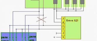
A – to the (+) “plus” terminal of the battery B1 and B2 – grounding points of the ignition system wiring harness C1 – grounding point of the wiring harness from the ignition coils
1. – M7.9.7 controller 2. – connector for connecting the ignition system harness to the instrument panel harness connector 3. – block with the main 30A fuse 4. – speed sensor 5. – electric idle speed control 6. – air flow sensor 7. – instrument sensor engine coolant temperature readings 8. – engine coolant temperature sensor 9. – throttle position sensor 10. – oil pressure warning lamp sensor 11. – rough road sensor 12. – electric fuel pump relay 13. – fuse (15 A) in the circuit electric fuel pump power supply 14. – ignition relay 15. – fuse (15 A) power supply to the ignition relay 16. – fuse (7.5 A) in the power supply circuit of the vehicle controller 17. – crankshaft position detection sensor 18. – oxygen flow sensor 19. – phase sensor 20. – knock detection sensor 21. – solenoid valve for canister purge 22. – diagnostic oxygen sensor 23. – spark plug coils 24. – spark plugs 25. – injectors 26. 26-27 – connector blocks connecting the ignition coil wiring harnesses to the harness ignition system wires 27. 28-29 – blocks connecting the ignition system wire harnesses with the injector control wire harness
Schematic electrical diagrams, connecting devices and pinouts of connectors
The ignition switch in cars of the VAZ family fails from time to time due to weakening of the contact posts or burning of the contacts inside it. It also happens that the cams of a plastic roller are produced. You can disassemble the lock and clean it, but it’s better to just replace it with a new one, considering that it costs pennies compared to imported locks.
But if connecting the wires together did not result in the starter operating (or it did not turn on the first time), check the solenoid relay on the starter. The contact spots on it may also burn out, which will prevent the circuit from closing normally. Alternatively, you can use a screwdriver to short-circuit the two large terminals on the solenoid relay (before doing this, put the car in neutral and use the handbrake). When closed, the starter should begin to spin vigorously. If this happens, remove and change the solenoid relay. If the starter rotates “sluggishly” when it closes, you will have to remove it and check the condition of the brushes.
All operations are performed with your own hands, without the help of car service specialists. Moreover, the price of an ignition switch on a VAZ2106 is up to 100 rubles. To replace it, you will need to know the pinout of the wires coming from it, for which the editors of the site 2 Schemes.ru have prepared a large reference material.
The ignition switch is designed not only to start the engine - it performs several functions at once:
- supplies voltage to the vehicle’s on-board network, closing the circuits of the ignition system, lighting, sound alarm, additional devices and instruments;
- at the driver’s command, turns on the starter to start the power plant and turns it off;
- turns off the power to the on-board circuit, preserving the battery charge;
- protects the car from theft by fixing the steering shaft.
How to remove the ignition switch on a Priora
Before carrying out work, it is necessary to remove the terminals from the battery.
Experts recommend using a proven algorithm: At the initial stage, you will need to get rid of the casing that hides the ins and outs of the steering column. The operation is simple and requires only a screwdriver or screwdriver to unscrew threaded hardware. The second stage involves unscrewing the special bolts. They are manufactured with tear-off caps and are disposable materials. This design approach provides a certain degree of security, minimizing the possibility of unauthorized access to starting the car. A chisel is used to unscrew them.
It is important to remember that they have a right-hand thread. Having torn the hardware out of place, you can finally get rid of them using long-nose pliers (curved or straight). Remove the clamp. Special bolts held the clamp installed on the steering column. The latter is installed to hold the lock. The dismantling work is completed by disconnecting the power plugs in order to have full access to working with the lock.
The latter is installed to hold the lock. The dismantling work is completed by disconnecting the power plugs in order to have full access to working with the lock.
Next, we purchase a new lock with an immobilizer and relearn it if necessary. Usually you can do it the first time. In some situations, transponders in keys are changed so that the standard protection can recognize electronic signals and unlock in a timely manner.
Removing the ignition switch, replacing the contact group and immobilizer coil of Lada Granta
Replacing the CV joint on a Priora fret with your own hands: video instructions
Tools:
- Ratchet wrench
- 10 mm head
- Medium Phillips screwdriver
- Small flat screwdriver
- Driver for socket attachment
- 8mm wrench attachment
- 24mm wrench attachment
- Chisel and hammer or electric drill
- Long nose pliers
Parts and consumables:
- Sandpaper (fine grit)
- Return spring (if necessary)
- Microswitch (if necessary)
- Contact plate on light guide (if necessary)
- Ignition switch contact group (if necessary)
- Bolt with shear head M6 – 4 pcs.
Notes:
Remove the ignition switch to replace it if its cylinder mechanism fails, to replace the contact group of the ignition switch, and also if it is necessary to replace the immobilizer coil.
Removing the ignition switch
1. Disconnect the wire terminal from the negative terminal of the battery.
2. Remove the steering column covers and left steering column stalk as described in this article.
Note:
For ease of operation, you can remove the steering wheel and the spiral cable drum device.
3. If the ignition switch O-ring was not removed when removing the steering column covers, remove the O-ring from the ignition switch.
4. By pressing the block lock, disconnect the ignition switch contact group wire block from the instrument panel wiring harness.
5. Using a thin screwdriver, pry the edge of the wiring harness block and disconnect the immobilizer coil wiring block from the instrument panel wiring block.
6. The ignition switch is secured with bolts with shear heads; these bolts are tightened until the heads come off. After this, use a chisel and a hammer to tear off the lock fastening bolts, as is clearly demonstrated in the second photo below.
Shear head bolt:
1 – threaded part;
2 – round head;
3 – turnkey shear head.
7. When the caps are already loose enough, you can unscrew them using long-nose pliers.
8. When all the bolts are unscrewed, remove the clamp securing the ignition switch to the shaft, and then the switch itself.
Disassembling and assembling the ignition switch
1. Remove the three screws securing the bracket to the switch body.
2. Remove the bracket from the housing.
3. Remove the ignition switch microswitch drive.
4. Press the plastic latch and remove the microswitch from the bracket.
Note:
To replace the microswitch, you need to unsolder the wires from its contacts.
5. Disconnect the wire block from the backlight lamp socket.
6. Using a screwdriver, unfasten the latch on one side of the ignition switch.
7. Then unfasten the two latches on the other side.
8. Remove the plastic cover from the switch housing.
9. Using a screwdriver, unfasten the two latches on both sides of the cover.
10. Remove the contact group and light guide from the cover.
11. Clean the oxidized or burnt contacts of the plate on the light guide with fine sandpaper.
12. If the contacts are severely damaged, replace the contact plate on the light guide. To do this, turn the contact plate so that its internal protrusions fit into the slots of the light guide and remove the plate along with the return spring. Replace a broken or cracked return spring.
13. Using a screwdriver, remove the immobilizer coil (if equipped).
14. Install the spring and slip ring on the light guide in the reverse order of removal
Please note that the protrusions on the inner surface of the light guide should be opposite the wide outer protrusion of the plate
15. Clean oxidized or burnt contacts with fine sandpaper. If the contacts are severely damaged, replace the contact group. To do this, you need to unsolder three wires from the contacts.
16. When assembling the switch, first install the light guide with the contact plate on the base of the contact group so that the long protrusion of the plate is opposite the stop on the base.
17. Place the cover on the base so that the top of the light guide fits into the hole in the cover. Secure the base to the lid with latches.
18. Install the cover with the contact group on the switch body in the reverse order of removal
Please note that the protrusion on the lock cylinder must be between two protrusions on the inner surface of the light guide
19. Install the microswitch in the reverse order of removal, making sure that the crack does not fall out of the groove in the bracket
20. Carry out further assembly and installation of the ignition switch in the reverse order.
21. Install new ignition switch mounting bolts. Tighten the fastening bolts evenly until their heads come off.
The article is missing:
- Photo of the instrument
- Photos of parts and consumables
- High-quality photos of repairs
We fix the most common problems
Then we begin to correct problems in the wiring system. Most often, problems in the ignition system are associated precisely with oxidation or chafing of the wire group.
Carefully pry (using a flat-head screwdriver) the plastic latches on the cover of the wire block and open it. It is important to remember, or better yet, note the location of the wires there, so as not to get confused during reassembly. If you are not a pro, then the easiest way is to record the location of the wires using a camera on your mobile phone.
We sequentially unbend the metal “antennae” and take out the wiring. During this operation, we will be able to clean the contacts and check their integrity.
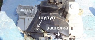
We go directly to the ignition mechanism, remove the wires located on the ignition system housing. To do this, use a screwdriver to press out the latches (they are plastic, so disassembling them is not difficult, but this must be done carefully) and remove the wiring from the housing.
The housing contains a contact group, which starts the vehicle systems. It is important to check its condition and possible problems. The part we have to pay special attention to is the moving contact. It needs to be disassembled and checked. To do this, we separate it from the stator contact group and disassemble it. Disassembly is carried out by simply pressing on this mechanism and turning it counterclockwise. As a result, the contact spring is separated and checked, and it is also possible to access the check of the car's anti-theft system.
Auto-assistance
VAZ 2114 ignition switch replacement
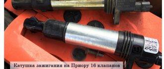
The starter, which is installed on the Lada Priora passenger car, has catalog number 2111.3708010-01. Its electrical connection diagram is similar to other brands of VAZ cars, but changes have been made to the design of the starter itself regarding the transmission of torque from the armature shaft. This starter is equipped with a planetary mechanism, which is driven by the armature shaft, and the planetary gear carriers rotate the shaft on which the overrunning clutch and the starter drive gear are located. Changes to the design have been made to make the “life” of the starter motor easier by increasing the torque with a planetary gearbox.
Malfunctions that lead to starter failure are divided into two groups: electrical and mechanical. The search for the cause of the failure usually begins with the electrical part if the starter armature does not show signs of life. First of all, check the 15 amp fuse F1. It is blue in color and is located on the right side of the floor tunnel in the area where the front passenger's feet are located. If it is intact, then you will have to check the functionality of the K3 starter relay, which is located in the mounting block. The culprit may also be a bad contact in the block at the main relay, which is why the starter relay will not work. And the ignition switch can also fail.
Next, you will have to check whether voltage is supplied to the contacts of the relay, which is called traction. If there is voltage, but the relay armature does not move (there is no click), then it will have to be replaced. If this relay is in working condition, but you cannot hear the rotation of the armature, then you will have to look at the battery terminals for oxidation, as well as the fastening of the wires going from the battery to the traction relay. If, when you try to turn on the starter, the armature does not rotate again, you will have to remove the traction relay and check whether its internal contacts are burnt. In addition, the reason for the armature not rotating could be its brushes, if they are worn out or stuck.
When the electrical part of the starter is working properly, its armature will rotate, but in order for the torque to be transmitted to the flywheel ring gear, the starter drive gear must be engaged with it. It is possible to find out the mechanical causes of a starter malfunction on a Lada Priora only after removing it from the engine and disassembling it. The most common malfunction is wear of the overrunning clutch, as a result of which the drive gear will not rotate, although it will engage with the flywheel ring gear.
Much less common are malfunctions associated with wear of the teeth of the starter drive gear and the flywheel ring gear. In this case, the grinding noise of the gears trying to engage will be clearly audible, but due to their wear this does not happen. There are also cases when the drive lever is disconnected from the traction relay armature, which prevents the starter drive gear from moving towards the flywheel.
Elimination of breakdowns of the anti-theft system
Communities Lada Priora Lada Priora Club Blog voltage on mass air flow sensor
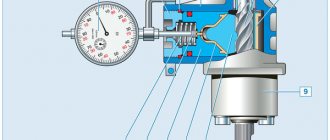
Sometimes the Priora does not start due to the immobilizer - it simply does not “see” the key. An immobilizer is an electronic anti-theft device that prevents the engine from starting without the original key. The principle of operation of the mechanism is shown schematically in the photo.
The principle of operation of the immobilizer
In the body of the original ignition key there is a transponder chip 3, which contains a complex electronic code. When the driver inserts the key into the ignition, the immobilizer is activated and the electromagnetic waves 2 of the electromagnetic coil 1 begin to read the encoded code. If the codes in the memory of both the immobilizer electronic unit and the transponder match, the engine starts; if there is an error during reading, the engine will not be able to start.
In the event of a breakdown, an anti-theft device can become a serious problem for the car owner, since the location of the micro-immobilizer - a relay that ensures the functioning of the main vital systems of the car - is almost impossible to find. The mechanism can be disguised as a fuse or controller and installed in the most unexpected places, otherwise the entire anti-theft system becomes meaningless. It is possible to revive a car if the immobilizer fails, but it is quite troublesome. If the transponder is damaged, try using a spare key. If the chip is working, but the system still does not “see” the key, you need to buy another one and reflash the electronic control unit.
The system may not respond to the key if the reading coil is damaged: in this case, the lock assembly with it will have to be replaced. To avoid causing problems with the immobilizer, you should not try to start the engine in severe frost or if the battery is discharged. It is not recommended to place keys near sources of strong electromagnetic waves (for example, a microwave oven). You cannot keep keys from different cars in one bunch, or remove the battery terminal while the ignition is on.
All problems associated with starting the engine can be resolved using the instructions described. A car is a complex mechanical and electronic system that requires careful handling and following certain rules during operation. Otherwise, a malfunction may occur at the most inopportune moment.
How to replace the ignition switch on a VAZ 2170-VAZ 2172?
VAZ 2110: repair of the ignition switch and ignition module
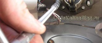
1. First, remove the negative terminal from the battery (How to do this, read the article: “Replacing the battery”), we strongly recommend that you do this, otherwise there may be a problem with the wiring (For example, the wires will be shorted, or moisture will get on them, which is very undesirable), after this operation is completed, crawl under the steering column and unscrew while there all the screws that secure the protective cover (There are seven screws in total, all of them are indicated by red arrows in both photographs below) and then remove it, but before that , first lower the lever that fixes the steering column down (Indicated by a blue arrow), otherwise the cover will not be removed.
2. Now look at the ignition switch, namely at the back part, there are two wires coming from it, you follow these wires and disconnect them at the place where they connect to other wires, for more details about these places, look visually at the two photos below:
3. Well, now the most difficult thing is to unscrew the bolts that secure the lock (They are all indicated by red arrows), in order to unscrew them, you need to apply a chisel to them obliquely and hit them with a hammer and chisel, as if trying to unscrew them (That you need to hit counterclockwise), and when the bolts come off, you can take pliers and finish the job with them, by the way, if you can’t get the lock out, then take a drill, drill bits and drill out all the bolts, but just be careful, don’t damage the steering column .
4. When the lock is removed, you can, in principle, change it and install a new one in its place, but we will still show how it is disassembled, in case you need to replace the contact group, in general, let’s get started, first bend the connector lock using a flat screwdriver (see . photo 1) and then, remove the terminals from the connector (see photo 2, they are removed using a thin screwdriver, any terminal has a latch for which it hooks, so you will need to press it with a screwdriver and just pull out the terminal, and so on with each ), then squeeze the plastic latches with your fingers (see photo 3) and pulling the metal body of the lock, separate it and the plastic cover as shown in photo 4.
Note! When you remove the terminals, remember how they were positioned (You can mark them), during reassembly all the terminals must fall into place, otherwise the wiring will not connect correctly and the car simply won’t start, or the wiring will shorten, be careful with this!
5. Finally, bend the two latches that are made of plastic (Be careful not to break them, see photo 1) and after that, remove the contact group from the plastic cover of the ignition switch (see photo 2), inspect the contact group after removal, inspect all contacts of the lock cover, if any contact is oxidized, then carefully clean it with sandpaper, if the contact is severely damaged, then replace the contact group with a new one or replace the lock assembly itself (If the lock is broken, the lock is assembled in reverse order of removal, do not forget about the terminals (see photo 4 for how they are located), they will have to go into the same places, when installing the ignition switch, insert the key into it and turn it from position 0 to any other and you can put the lock on your place, and when everything is assembled and installed, replace the transponders in the ignition keys, otherwise the car will not start (For more details about this, see the video clip, which is located at the end of the article).
Note! If you suddenly need to retrain a key, then retrain it, this is done easily (How to retrain a key, read the article: “Retraining car keys”), but essentially this operation should not be affected if you replace the transponders, in general, after replacing the transponder , start the car, if it doesn’t start (the ignition should light up, but the starter will not respond), then relearn the key!
Additional video: Look in more detail at the process of replacing the ignition switch in cars of the tenth family (In Priors, everything is done exactly the same way), so that you have at least a little idea of how to remove the nuts that secure the ignition switch, how to then unscrew them with pliers, and so on Further.
Note! As for the transponder, watch the second video, which is located in exactly the same way, just below:
The ignition system of any car includes various elements and mechanisms to ensure the most optimal start of the power unit. One of the main components is the Priora ignition switch, with which the driver can start the engine. We will tell you more about the malfunctions, as well as the replacement of the seal below.
Repair instructions
The location of the 3Z is known to everyone - this unit is located directly under the steering wheel. To properly replace or repair a device, you must follow the instructions:
- First, disconnect the battery and remove the plastic steering column cover, which is secured with bolts.
- Next, press out the fastening and disconnect the connector with the 33 wiring from the control panel wiring block. When unplugging, be careful not to damage the plug.
- Having done this, you will also need to disconnect the plug with the 3Z wires from the connector with the wiring of the immobilizer control system. Using a hammer and chisel or a drill, you need to remove the four breakaway screws and remove the assembly from the steering column. You can't just unscrew these bolts. VAZ engineers decided to use this method of installing the protection in order to protect car owners from possible thefts. This method of fastening, as you can guess, makes it very difficult to dismantle the protection, so at this stage you will have to tinker. In any case, the bolts can be dismantled or drilled out, but instead you will have to purchase new ones in advance.
- After completing these steps, you can bend the connector mount with wiring from the 3Z. The terminals with wires are removed from this connector. Next, you need to compress the latches again and dismantle the plastic cover of the device itself. If you plan to simply change the node, then this can be done at this stage. We suggest that you familiarize yourself with more detailed information on repairs - it is quite possible that simple steps will restore the unit’s functionality and save money.
- So, if you decide to repair the mechanism, then at this stage you need to press out two more plastic clips and remove the contact group from the cover.
- Next, it is necessary to carry out a thorough visual diagnosis of the contacts. If you notice that the contacts have oxidized or burnt, you can restore their functionality by cleaning them using fine-grained sandpaper. Get rid of oxidation and plaque, but do not go too hard so that the contacts do not wear off. If the damage to the contacts is too severe, then cleaning will not solve the problem - you will only need to change either the contactor itself or only the contact group.
- If everything worked out with the contacts, then you can assemble and install the protection. During assembly, pay attention to the position of the terminals with the wiring in the connector; under no circumstances should they be mixed up.
- After completing these steps, install the locking device back into place, while pre-sinking the locking rod of the anti-theft unit. To do this correctly, install the key in the 3Z and turn it to any position, the main thing is that it is not in the “0” position. If the key is replaced, then the transponders must also be changed - these are special electronic code components on the head of the key. If you do not do this, then you will also have to carry out the training procedure, as well as change the lock cylinder on the trunk and doors, and this is a rather labor-intensive process. Otherwise, you will have to use the old key to open the doors and trunk and the new one to start the engine. Agree, this is completely inconvenient, but this is only relevant for those car owners who have changed their license plate.
Priora won't start, starter turns
Possible malfunction
| Diagnostics | Remedies | |
| There is no gasoline in the tank | On the instrument panel the fuel level indicator is at zero. | Pour gasoline |
| Battery is low | The voltage at the battery terminals without load is less than 12V. When trying to start the car, a crashing sound is heard from under the hood. | Charge the battery or replace it with a new one |
| Oxidation of battery terminals or wire terminals, their fit is not tight | When you try to start the engine, the voltage in the on-board network drops much more than at the battery terminals. In this case, a crash may be heard under the hood. | Clean the contacts, lubricate them with petroleum jelly and tighten the terminals |
| Unreliable connection of electrical circuits of engine control and power supply systems | Check the connections of the connectors and the reliability of the contacts in the blocks. | Fix faulty wire connections |
| Increased resistance to rotation of the crankshaft (scores on the shafts, bearing shells, cylinder-piston parts, deformation of the shafts, frozen engine oil, jammed generator, jammed coolant pump) | The crankshaft turns slowly. If the engine is started in severe frost, and the engine was working properly the day before, then most likely the engine oil has frozen. If you hear extraneous noise when starting the engine, check the free rotation of the pump and generator pulleys. | Use the recommended engine oil. Repair the engine. Replace the pump and generator. |
| Malfunction in the ignition system | Check for spark. | Check the circuits and devices of the ignition system. Replace faulty system elements. |
| The high voltage wires are connected in the wrong order or the wire is disconnected | Inspect. | Connect the wires in the correct order |
| The timing belt is broken or the belt teeth are cut off | Open the front timing cover and check. | Replace timing belt |
| Disturbed valve timing | Check the marks on the crankshaft and camshaft pulleys. | Set the correct shaft position |
| Malfunction of the computer (brains), its circuits, crankshaft position sensor or coolant temperature | Check the supply of +12V to the ECU, the sensor circuit, and the absence of damage to the sensors themselves. | Replace ECU, sensors. |
| The idle air regulator (IAC) or its circuits are faulty | Check the idle air control. When starting the engine, lightly press the gas pedal. If the engine starts and stalls when you release the gas pedal, the sensor is faulty. | Replace sensor |
| The fuse is blown or the main relay of the control system is faulty | Check fuse and relay. | Eliminate the cause of the blown fuse. Replace fuse and relay |
| Fuse blown, fuel pump relay. Circuit, relay or pump is faulty. | When the ignition is turned on, there is no sound of the pump running. Check the fuse. Apply voltage to the pump from the battery. | Clean contacts, replace faulty circuits, replace fuse, pump and relay. |
| The fuel filter is dirty, the water in the fuel line is frozen, the fuel line is damaged | Check the pressure in the fuel rail and the condition of the fuel lines. | Replace the filter, blow out or replace the fuel lines. |
| Insufficient pressure in the fuel rail | Check the pressure in the fuel rail, the pump strainer and the condition of the fuel lines. | Clean the filter. Replace pump, fuel pressure regulator |
| Faulty injectors or their power supply circuits | Check the injector windings with an ohmmeter. Check the chains for breaks. | Replace injectors, replace chains |
| Air leak into the intake tract | Inspect the joints and fittings of the hoses and clamps. During start-up, turn off the vacuum brake booster and plug the receiver fitting. | Eliminate air leaks, replace vacuum booster |
Pinout of the lighting control unit on Priora
The module is connected to the vehicle’s on-board network via chip No. 1118-3724500. The standard terminal pinout on a VAZ 2170 looks like this:
- G56b – for the gearbox for adjusting head lighting devices;
- 58b – output from lighting and instruments;
- 31 – neutral earth cable;
- Xz – 12 volts from pin 15 of the ignition switch;
- 56 – relay switch for high and low headlight modes;
- 1, 3 – connection of fog lights;
- 2, 4 – sending a signal to the controller;
- 58 – dimensions;
- 30 – power supply from the ignition switch design.
The standard electrical connection diagram (pinout) for the VAZ 2170 Priora has its shortcomings and strengths. However, thanks to the simple design, you can eliminate defects yourself, without the involvement of service station specialists.
Lock key and keyhole
A bent key can also cause this type of failure. Opening frozen door locks and the trunk of a car (if all the locks are opened with one ignition key) and using the key for other purposes will certainly lead to its bending and deformation of the working area over time. After this, the key does not turn in the ignition or even cannot enter the keyhole at all. This factor is eliminated by leveling the key blade with the usual tapping of a hammer.
If the problem lies in the secret of the lock, namely in excessive wear of its lamellas, then you cannot do without dismantling and disassembling the mechanism. As a rule, repairing a secretion is very difficult and troublesome; most often it is completely replaced. But what to do when the ignition switch is jammed somewhere far from home, and it is not possible to replace unsuitable parts? In this case, you can remove the secret from the lock body and remove all the springs and lamellas from it. This process will allow you to start the car even with a regular screwdriver, which is quite enough to get to the nearest spare parts store or repair service.
Car alarm connection points for Lada Priora 2011
Author RA9UBD
Ignition switch: + 12V – brown Starter – red IGN – blue/black
Tidy: Tacho signal - brown/red Handbrake - brown/blue (For more details, see Diagram 1)
Connector X3 (See Fig. 1) BCM: Driver's door switch - blue/black Right front door switch - brown Rear door switches - gray/red Trunk switch - yellow/red Opening the trunk (low-current input, possible without a relay, additional channel directly to alarm) – blue/red
Connector X1 (See Figure 1) BCM: Turns – blue, blue/black
Ts.Z. - brown; The wire is located inside the driver's door, in the harness from the button block. (See Diagram 3 for details)
Hood end cap – white/black; Connector X2-17 (If an engine temperature sensor is used, then according to scheme 2)
The block is located behind the panel, near the gas pedal. To remove the block, remove the left and right panels, unscrew the two 10mm nuts, left and right, securing the block.
Connection to central locking
When connecting the central locking (see diagram 3), if you connect only to the brown wire in the driver's door, then all doors will close and only the driver's door will open. To open the remaining doors, you need to use a wire in the alarm for two-step opening of the central locking system, and connect according to the diagram below.
The remaining doors are opened by the second impulse, relay K1. Relays K2 and K3 are also activated; they are needed to block the right power windows. If this is not done, then when you open the remaining doors, the right windows will open slightly for 0.8 seconds, i.e. from the impulse to open the central locking, the second step. It is necessary to block the power windows due to the peculiarities of the electrical circuit of the Priora doors.
If the configuration does not include power windows on the rear doors, then relay K3 does not need to be installed, and accordingly, cell X1-11 in connector X1 is not used. (The color of wire X1-11 is not known.) If the configuration does not include power windows at all, then there is no need to use relay K2.
Standard ignition switch - article number, price, how it works, device
The module on Priora does not work directly with the components that initiate the engine start. For it to work properly, you need to wait a few seconds before starting until the fuel pump creates the required pressure. On the Priora, only wires are connected to it - the paths along which messages pass from the ignition switch to the electronic control unit.
The ECU of the Priora car just receives data about the position of the key and can crank the starter if this operation is “not blocked”. Due to a breakdown, it can only turn on the ignition, leaving the battery to work.
After the ECU key has turned, it gives commands to several parts at once. When you turn on the second position, let the fuel pump run for 5 seconds so that it pumps fuel from the tank closer to the engine.
When the starting process itself begins, the starter rotates - the force it creates goes to the crankshaft;
the ignition system element converts the low voltage current coming from the battery into a high one so that the spark plugs are “charged” and give a spark at the right moment;
The injector creates the first batch of air-fuel mixture to put it into the chamber, where everything is ready for it - the pistons “move”, the spark plugs spark.
In the module itself, everything is simple - there is a cylinder with a return spring inside, between the coils there is a locking ball that does not allow it to curl up more than necessary, and a locking rod holds the structure in place. Finally, as a complication of the entire system, there is an “immobilizer” - an anti-theft system that you can install yourself. It just takes a long time to set it up.
A regular kit with a master key and several door cylinders (with an immobilizer) costs from 1,800 - 2,000 rubles, catalog number - 2170-3704005. A set without a master key (without an immobilizer) can be purchased for 1,200 – 1,400 rubles, article number -2170-3704006.
Basic faults
Usually the module is “sinned” when the battery is dead - nothing will turn on, even the ECU will not receive a signal. You can solve everything by charging the battery or installing a new one. But if you are sure that the key in the ignition switch has turned, but there is no “effect”, then the problem is in the module.
- Firstly, one of the dangerous problems is a faulty locking rod. As was said, it does not allow you to remove the key when it is in position I or II. If you accidentally notice that the key falls out, try to replace the block as soon as possible. It happens that replacement is taken due to an immobilizer error. This can only be done as a last resort, having accurately checked all possible “escape routes”, because reconfiguring the ECU will take a lot of time.
- Secondly, the wiring connected to the unit may become damaged, and it will become “cut off” from the Priora’s electronic control unit. It is necessary to ring all sections of the wiring and change it. In the same group of problems is the fuse relay. If the fuse is blown, the engine will not start.
- Thirdly, the spring may become deformed or break. This manifests itself in the fact that after cranking the starter and starting the engine, the key does not return to position I.
How to replace the ignition switch on a Priora
In order not to think about how much it costs to repair an ignition switch in a service center, go through the update process yourself. If the car does not start, consult a specialist. We will talk about the features of the ignition switch and the process of replacing it yourself.
What is the device?
The ignition switch is a special device that supplies direct current to the starter traction relay. Such impulses come from the battery and are activated when the lock is turned on. Without the correct operation of the device, the car will not function fully.
Design Features
The mechanism includes two main parts. The ignition key is placed in the lock cylinder, which puts the car into operating mode and activates the lock itself. The second part is the contact group. It closes in a certain sequence, depending on the position of the key in the cylinder.
Why the system might break down
The need to replace the lock may arise for a number of the following reasons:
- wear and tear of individual parts. Burnouts or oxidation of the system drives are common;
- incorrect contacts. Violation of such circuits leads to combustion, oxidation and lack of working abilities;
- cylinder wear. The breakdown is manifested by difficulties when using the key;
- Lost car key. A trivial but compelling reason for replacement.
Troubleshooting
The ignition switch on a Priora often fails due to improper use. The first step before replacing the device is to disconnect the battery. To do this, remove the terminal. Also remember to remove the steering cover and disconnect the electrical connectors.
The Priora ignition switch is bolted to the steering rack. You won't be able to unscrew them with a screwdriver or keys. You need to use a hammer or chisel. Otherwise, use an electric drill, which can remove the bolts.
When removing the bolts, they may break. There is no need to worry about this; such a part can be easily and quickly replaced. To simplify the work of replacing the lock, simple bolts or screws are installed in the future. They can be unscrewed with standard tools.
Replacing the ignition switch on a Priora includes checking the voltage of each contact. This process prevents unwanted problems with the new lock. In order not to confuse the connection of the contact group, their “natural” arrangement is first recorded. This simplifies the work with replacement and provides you with a hint when completing the assembly of the mechanism.
If the Lada Priora ignition switch is not replaced, then problems may arise with its components. Replacing a contact group involves the following process:
- The casing is removed and the lock is pulled out.
- The correct pin connection sequence for reconnection is recorded.
- According to the recorded connection principle, a new contact group is distributed.
- Place the lock in its original position, covering the steering wheel with the removed cover.
Replacement with immobilizer
An immobilizer is used by car owners to block movement. This is a special anti-theft agent that is installed next to the lock. Replacing the ignition switch with an immobilizer must be done extremely carefully so as not to damage both systems.
How to remove the ignition switch on a Priora without damaging the protective mechanism? The car owner must pull out the lock without touching the immobilizer. To do this, it is worth moving away the “unnecessary mechanism”, devoting time exclusively to the lock. Further repairs are carried out according to the standard scheme.
Self-replacement
Before changing the ignition switch on a Priora, you must take into account that this operation will be more labor-intensive than a similar process when working with classic VAZ car models.
A motorist can complete this job in an hour. He also needs to stock up on tools:
- Phillips screwdriver or screwdriver with a similar bit;
- hammer 0.5 kg;
- a pointed chisel or punch with a blade width of 8–10 mm;
- hex head 10;
- ratchet equipment with middle extension.
Due to the fact that the repairs are supposed to be carried out in dark, cramped conditions, it is worth thinking about local comfortable lighting. Some find it convenient to work with a car lamp equipped with a hook or magnet for hanging in any conditions. Some motorists are accustomed to using a bright headlamp with LEDs for such purposes.