Anti-theft protection for connector
The connector also helps thieves.
By connecting to it, the attacker can easily turn off the car alarm, and his further actions will be predictable. The whole problem is that the thief knows in advance the location of the plug, which simplifies his life, and connects to it immediately after opening the car door. The plans of attackers can be ruined if the diagnostic plug is moved to another place in the car. This is most often done at service stations, so it is recommended to entrust this operation to specialists. If you do this yourself, you should first think about where to put the plug so that it “does not catch your eye.”
In words, everything is quite simple: remove the plug, disconnect it, put it in a new place and reconnect the wire block. In fact, you will have to dig a fair amount into the inside of your Priora, but it’s worth it if you want to take care of protection against theft.
The diagnostic plug will make life easier for the owner of a Lada Priora - instead of torturing yourself with a tool in your hand, digging in the engine compartment, you just need to get this “adapter”, find out the reason and only then start repairing.
The operation of the car control system is checked using special devices. Therefore, to test the vehicle, you need to find the Priora diagnostic connector and connect the equipment. The work takes minimal time. You just need to know the rules for connecting and using the test device.
Connector type
The Priora diagnostic connector is designed according to the OBD-2 principle. This is one of the most common and reliable systems. It communicates with the ECU - this is an electronic control unit. Such a block serves as a special assistant for car enthusiasts, which helps conduct diagnostic studies.
For Priora, several sockets are used to create a connection between two systems, namely:
- ground or ground with socket four and five;
- constant 12 Volts – 16;
- socket for direct diagnostics – 7.
The use of other nests is less common. They are designed to provide additional connections with the electronic control unit and “L” lines. There is no need to connect them yourself. To do this, you need to have experience working with special software modules of the car. Such procedures are quickly performed in technical services.
Connection rules
All equipment is connected to the OBD-2 type connector using special “plugs”. If you have not worked with the connection directly, you can use an auxiliary element - a plug connector. It is recommended to pay attention to the “plus” and “minus” values for the installed equipment. To be sure of the correct connection, take the car’s battery in working condition as a basis. Otherwise, the signal will not be given correctly.
-FOOTNOTE- If you are not confident in your abilities, contact the technical service. This way you will save yourself from wasting time and will be able to get a car with the connector working correctly.
Location
Often faced with a problem where the diagnostic connector is located. In each car they are installed differently, taking into account the specifics of the entire structure. As for Prior, everything here is done quite cleverly. If you don't know the exact location, it will be difficult to find.
Car manufacturers have placed a diagnostic connector in the glove box. You can find it on the passenger side in the interior. Simply put, look in the glove compartment. If you contact service centers, specialists will immediately find the required design. Beginners need to be more vigilant in this matter.
It is best to work according to already compiled instructions. Let's take a closer look at the process:
- We completely open the glove box and clear it of foreign objects to make it easier to work.
- The glove compartment should hang on plastic guides on each side.
- We press on the side plates so that the small door opens further. This will make it easier to work and find the Priora diagnostic connector.
- We pull out the tabs on the side and completely remove the glove box from the latches.
- Provides access to the input plug for diagnostics. Now he is free and ready to go.
Access to the device is open. The following operations directly depend on the purpose of “opening” your car. More often they get to the connector to reconnect it or check the correct signals from the ECU. This way his work will be adjusted and will not create problems or unforeseen situations.
Glove compartment in a Lada Priora car
OBD 2 pinout
Pinout of the Lada Priora comfort block
The layout and purpose of the contacts in the OBD 2 connector are determined by the standard.
Numbering of plugs in the connector
General description of plugs:
- 1 - reserve, this pin can output any signal that the car manufacturer sets;
- 2 - channel “K” for transmitting various parameters (can be designated as J1850 bus);
- 3 - similar to the first;
- 4 — grounding of the connector to the car body;
- 5 — diagnostic adapter signal grounding;
- 6 - direct connection of the CAN bus contact J2284;
- 7 — channel “K” according to ISO 9141-2 standard;
- 8 - similar to contacts 1 and 3;
- 9 - similar to contacts 1 and 3;
- 10 — pin for connecting the J1850 standard bus;
- 11 — pin assignment is set by the vehicle manufacturer;
- 12 - similar;
- 13 - similar;
- 14 - additional pin of CAN bus J2284;
- 15 — channel “L” according to ISO 9141-2 standard;
- 16 - positive output of the on-board network voltage (12 Volts).
An example of a factory OBD 2 pinout is the Hyundai Sonata, where pin 1 receives a signal from the anti-lock braking system control unit, and pin 13 receives a signal from the control unit and airbag sensors.
Depending on the operating protocol, the following pinout options are possible:
- When using the standard ISO 9141-2 protocol, it is activated via pin 7, while pins 2 and 10 in the connector are inactive. For data transmission, pins numbered 4, 5, 7 and 16 are used (sometimes pin number 15 can be used).
- With a protocol type SAE J1850 in the VPW version (Variable Pulse W >
Is it possible to move the diagnostic connector to another location Priora
The question often arises in the minds of motorists: can they choose another location for the AR or not? Is it possible to hold such an event on your own? Car owners are interested in this issue, since car thieves know where the DR is located, in particular on the Priora, and are easily able to disconnect it from the alarm. But if this element is installed in another place, then it is quite possible to complicate the theft procedure significantly. Therefore, in this way it will be possible to prevent a possible crime.
Let’s say right away: installing a diagnostic connector in another place in the Lada Priora is quite possible, but experienced specialists advise resorting to such a service at a service station. There, qualified employees will carry out the transfer of this part carefully and accurately. In the event that the car owner plans to perform such an operation with his own hands, he will have to act in stages, especially by experienced drivers who understand connecting and disconnecting the electrical equipment of the car.
- carefully and accurately disconnect the wires from the connector;
- without haste, remove the device from the socket;
- move the diagnostic connector to the selected location;
- reconnect the connecting wires.
Attention! Experienced experts advise removing the connector yourself next to the gear shift knob or to the left of the steering column.
When another area for AR is selected and the planned manipulation is performed, only you are now aware of where exactly the connector is located. But, note, the hijackers will not be able to react in time to where the area of interest is located.
General recommendations for connecting to the diagnostic connector
Replacing knock sensor Priora 16 valves
p, blockquote 49,0,0,0,0 —>
- Some sources indicate various methods for self-diagnosis of a car by connecting jumpers to the OBD connector. In emergency cases this is justified. If you have the opportunity, time and money (now very little, even with an on-site visit) for diagnosis by a specialist, it is better to resort to his help.
- If you have skills in working with a computer or Android devices, you can purchase a simple ELM327 scanner and then diagnose the engine yourself. More expensive multi-brand scanners such as AUTOCOM allow semi-professional diagnostics of most car brands. You can buy expensive diagnostics by sharing with your garage neighbors or co-workers. Such diagnostics can generate profit by providing “crappy” services.
- Do not obstruct the connector. After purchasing a car, try to find its location, as it may suddenly come in handy.
- If the scanner has difficulty entering the connector, do not use excessive force; check whether the contacts are bent or whether there are any foreign objects (paperclips, other small items) in the sockets. Sometimes, under increased load, the connector falls inside the socket, and you have to disassemble the casing.
- Do not connect dubious scanners or various homemade products to the connector. Since the connector is directly connected to the vehicle's control units, an incorrect connection can cause damage to the vehicle and subsequent repairs will be costly.
Read this article about how to diagnose a car yourself.
Video - where is the OBD 2 connector located on the Renault Scenic:
p, blockquote 51,0,0,0,0 —> p, blockquote 52,0,0,0,1 —>
12-pin rectangular connector (lada 12 pin)
A Ground B L-line of engine diagnostics (including the line for reading slow self-diagnosis codes), ABS (8192-Baud Serial Data) (not always wired) C AIR (not always wired) D SES-Lamp - self-diagnosis lamp line (not always wired) E K diagnostic line (160-Baud Serial Data) F TCC (not always wired). On some models - +12V power supply G Fuel pump control (not always wired) J K-line for airbag diagnostics (AirBag) (8192-Baud Serial Data) M K-line for engine diagnostics, ABS
16-pin trapezoidal OBD-II connector (lada Obd-2 16-pin)
2) J1850 Bus+ 4) Body ground 5) Signal ground 6) CAN-High line, J-2284 7) K-line diagnostics (ISO 9141-2 and ISO/DIS 14230-4) 10) J1850 Bus- 14) Line CAN-Low, J-2284 15) L-line diagnostics (ISO 9141-2 and ISO/DIS 14230-4) 16) +12V power supply from battery
When is pinout required (device chips) and how to do it
All car parts fail sooner or later. There are times when they need to not only be repaired, but replaced. The instrument panel may also break, causing it to be removed and a new one installed in its place. This work is easy to do with your own hands if you have at least the slightest knowledge of mechanics. If you are well versed in your Priora (sedan), then you need to perform the pinout in this way:
Very often, motorists cover the panel with a special LED strip to achieve even lighting. You can also use CMD diodes, which can be easily fused into glass with a soldering iron. To do this, you need to disassemble the dial and solder diodes directly under the base of the hands.
If you understand the purpose of all the contacts, and also know the purpose of a particular connector on the panel, then you can easily do the pinout yourself. The main thing is to carry out everything strictly according to the instructions so that the connection is successful and the panel continues to function efficiently. If you know which is better to install a tidy: with a canbus or a regular one, then it’s better to ask professionals who understand this. If you have no experience in such work, and you do not understand the purpose of certain wires, then the technical service will help you improve the operation of the instrument panel. Of course, you will have to pay for this, but you will not waste your time, and the work will be done efficiently.
What is a diagnostic connector according to the OBD2 standard?
Replacing the upper engine mount of a Priora guitar
p, blockquote 5,0,0,0,0 —>
A little history
Manufacturers first started thinking seriously about automating vehicle diagnostics in the 70s. It was then that electronic engine control units appeared. They began to be equipped with self-diagnosis systems and diagnostic connectors. By closing the connector contacts, you can diagnose faulty engine control units using blink codes. As personal computer technology was introduced, diagnostic devices were developed to interface connectors with computers.
p, blockquote 6,0,0,0,0 —>
The emergence of new manufacturers on the car market and expanding competition predetermined the need to unify diagnostic devices. The first manufacturer to seriously approach this problem was General Motors, which introduced a universal information exchange protocol via the ALDL Assembly Line Diagnostic Link interface in 1980.
p, blockquote 7,0,0,0,0 —> adsp-pro-1 —>
In 1986, the protocol was slightly improved, increasing the volume and speed of information transfer. Already in 1991, the American state of California introduced a regulation according to which all cars sold here followed the OBD1 protocol. It was an abbreviation for On-Board Diagnostic, that is, on-board diagnostics. It has greatly simplified life for companies servicing vehicles. This protocol has not yet regulated the type of connector, its location, or error protocols.
p, blockquote 8,0,0,0,0 —>
In 1996, the updated OBD2 protocol had already spread throughout America. Therefore, manufacturers wishing to develop the American market were simply forced to comply with it.
p, blockquote 9,0,0,0,0 —>
Seeing the clear benefit of unifying auto repair and maintenance, the OBD2 standard has been extended to all gasoline-powered vehicles sold in Europe since 2000. In 2004, the mandatory OBD2 standard was extended to diesel cars. At the same time, it was supplemented with Controller Area Network standards for data exchange buses.
p, blockquote 10,0,0,0,0 —>
Interface
It is wrong to believe that the OBD2 interface and connector are one and the same. The interface concept includes:
p, blockquote 11,0,0,0,0 —>
- the connector itself, including all electrical connections;
- a system of commands and protocols for information exchange between control units and software and diagnostic systems;
- standards for the execution and location of connectors.
The OBD2 connector does not necessarily have to be a 16-pin trapezoidal design. On many trucks and commercial vehicles they have a different design, but the main transmission tires in them are also unified.
p, blockquote 12,0,0,0,0 —>
In passenger cars produced before 2000, the manufacturer could independently determine the shape of the OBD connector. For example, on some MAZDA vehicles, a non-standardized connector was used until the 2003 model year.
p, blockquote 13,0,1,0,0 —>
This is often a challenge for inexperienced auto electricians. The most common connector locations are:
p, blockquote 15,0,0,0,0 —>
- near the driver's left knee under the dashboard;
- under the ashtray;
- under one of the plugs on the console or under the dashboard (in some VW models);
- under the handbrake lever (often in early OPEL);
- in the armrest (occurs in Renault).
p, blockquote 16,0,0,0,0 —>
The exact location of the diagnostic connector for your car can be found in reference books or just Google it.
p, blockquote 17,0,0,0,0 —>
In the practice of an auto electrician, there are cases when the connector was simply cut off or moved to another location during repairs after accidents or modifications to the body or interior. In this case, its restoration is required, guided by the electrical diagram.
p, blockquote 18,0,0,0,0 —> adsp-pro-2 —>
Canbus operation
Let's take a closer look at the operation of the CAN bus on a car. As described earlier, it is a twisted pair of two wires twisted together. On a car, this bus is serial, that is, data is transmitted alternately along one or the other wire. In this case, electrical appliances are powered by another thicker wire.
The question may arise why the CAN bus on a car is made in the form of two wires if data is transmitted only over one. And why is a serial interface used at a lower speed than a parallel one? To save material, it would be more logical to make it with one wire, especially since such systems are used in industry. It's all about electrical, electromagnetic and other interference that is on the car. This interference creates an extraneous signal on the bus, and when using a single-wire design, this signal can lead to equipment failure. If the bus is made in the form of two wires twisted together, the so-called twisted pair, then an extraneous signal will be generated in both wires, but since they are twisted. The receiver receives the signal through the signal wire and removes repeating pulses arriving through the second wire.
Another feature of the CAN bus is the transmission of data in both directions, both from the control to the actuator and vice versa. That is, if a signal to turn on comes from the lamp switch to the lamp, then a signal is sent from the lamp to the switch whether the lamp is on or not. Also, when transmitting data over the bus, it is received by all equipment connected to it, and not by the specific equipment to which this data is addressed.
Pinout of diagnostic connector VAZ 2114
Pinout and where is the diagnostic connector for VAZ-2112
Diagnostics of modern car models is carried out using a special diagnostic connector. It connects to a computer, which analyzes the current state of the vehicle, determines the malfunction and indicates it. If you have the appropriate equipment, you can look for breakdowns even at home. However, not all VAZ-2112 owners can find the diagnostic connector right away. Today we’ll talk about its location on the classic panel and on the Europanel. In which part of the car should I look for the required socket?
Where to look for the connector
It is important to know that on different cars the required socket is located in different parts of the car. Moreover, on some AvtoVAZ models it may be in a completely different place compared to another car
Let's look at several VAZ cars as an example:
- on the VAZ-2112, as well as on the 2110, as well as 2111, the socket is located to the right of the driver’s seat, immediately under the column;
- on models 2108, 2109 and 21099, the socket you need is located under the glove compartment, on a special shelf;
- on cars with a europanel it can be found in the center of the console, near the cigarette lighter. A special decorative cover is used to disguise it;
- on Lada Kalina cars, the connector can be found near the gear shift lever. As is the case with cars with a Europanel, it is hidden under a special cover;
- on a Priora you need to look for it right behind the glove compartment, on the wall.
Thus, on the VAZ-2112 the diagnostic connector is located on the right side of the driver’s seat. It is located immediately under the steering column and, in principle, is not so difficult to find. Inspect the bottom of the panel.
Pinout
Knowledge of pinouts may be required if a car enthusiast wants to make an adapter for computer diagnostics with his own hands, or if you need to connect without one. Experts recommend buying ready-made devices without the need to make a plug yourself. However, if you do not have such an opportunity, and diagnostics need to be carried out urgently, we will consider two main pinout options used on VAZ cars of various years of manufacture. Until 2002, AvtoVAZ products used the following pinout option:
- The 4th and 5th pins are GND outputs.
- Pin 16 – +12 V (power line).
- The 7th contact is the diagnostic line itself.
Since 2002, the pinout scheme has changed significantly. Now it looks like this:
- Pin H – +12 V (power line).
- Contact G – +12 V for the fuel pump.
- Pin A – GND output.
- Contact M – diagnostic line.
There is one important note to note regarding this diagram. If you connect the connector without a block, but directly, it is recommended to use the charge from the cigarette lighter as a source of electricity
The peculiarity of this pinout is that contact H is not always routed in the car. The use of G is also not recommended because high frequency current is supplied. This can have a negative impact on the adapter, even to the point of burning it out. However, cases of burning out the fuel pump connector are quite rare. Therefore, if you wish, you can also use this option.
As you can see, the pinout on VAZ cars of different ages is sometimes very different. Therefore, we advise you to look at the registration certificate of your car and find out what year it is made. On older vehicles you will not find the new pinout design as it did not exist yet and on newer vehicles the old design was no longer used.
Pinout of diagnostic connectors for VAZ and GAZ cars
Currently, the vast majority of cars have an OBD2 diagnostic connector (trapezoidal 16-pin block, usually located in the steering wheel area). Through this connector you can connect diagnostic equipment to diagnose your car, as well as connect on-board computers and other devices that work through the diagnostic connector.
People often have questions about the pinout of diagnostic blocks for some cars. In our store there are various adapters for different models. But if you forgot to order an adapter for your car, you can try to make it yourself, or connect the adapter directly. To do this, we have prepared for you a short review on the pinout of the OBD2 socket, the pinout of the sockets for VAZ and GAZ cars.
Why is diagnostics needed?
Design and features of the Lada Priora car starter
Let's first figure out why we need to diagnose faults and whether this is required specifically for your car.
The main advantage of diagnostics is the ability to save money, time and modern nerves. If the car begins to behave inappropriately, some extraneous sounds appear, the stable operation of the engine is disrupted, then there are two options:
- To study all systems manually by dismantling and testing would waste a lot of time and nerves. The probability of finding the cause of the breakdown is far from 100%!
- Conduct computer diagnostics yourself by connecting a special adapter or cable to the computer. The program will scan the car and be able to issue the appropriate error codes. After studying our material with error codes, you can easily find the reason why the car began to behave abnormally.
Is it worth going to a service station?
The quality of diagnostics at a service station is often not much different from an independent check. Having an adapter and cable to connect the device allows you to deal with the problems of your own car without outside interference.
By contacting a service station, they can diagnose you with the same equipment, but they will only ask you for a decent amount of money. If you do not control the progress of the check yourself, technicians may claim to have found other errors that in reality do not exist.
The result of visiting a dubious service station for diagnostic purposes can be serious financial costs and a long absence of the car at your disposal.
Example of an adapter with cable
The only option when it is worth contacting a car service center is the lack of diagnostic equipment and the presence of good friends among car mechanics.
We recommend: Reasons for increased fuel consumption
Pinout diagram for OBD2 connector connection
p, blockquote 19,0,0,0,0 —>
The connection diagram for the pins of a standard OBD2 16-pin connector, used in most modern passenger cars, is shown in the figure:
p, blockquote 20,0,0,0,0 —>
p, blockquote 21,0,0,0,0 —>
p, blockquote 22,0,0,0,0 —>
- installed by the manufacturer;
- J1850 bus;
- installed by the manufacturer;
- car weight;
- signal ground;
- CAN bus high level;
- K-Line bus;
- installed by the manufacturer;
- installed by the manufacturer;
- J1850 bus;
- installed by the manufacturer;
- installed by the manufacturer;
- installed by the manufacturer;
- CAN bus J2284;
- L-Line bus;
- plus with battery.
The main ones for diagnosing are CAN and KL-Line buses. In the process of carrying out diagnostic work, they interrogate the vehicle's control units by exchanging information using appropriate protocols, receiving information about errors in the form of unified codes.
p, blockquote 23,0,0,0,0 —>
In some cases, the diagnostic device cannot communicate with the control units. This is most often due to a CAN bus malfunction: a short circuit or open circuit. Often the CAN bus is closed by faults in control units, for example, ABS. This problem can be solved by disabling individual blocks.
p, blockquote 24,0,0,0,0 —>
If communication via OBD diagnostics is lost, first check whether the original radio is installed in the car. Sometimes a non-standard car radio short-circuits the K-Line bus.
p, blockquote 25,0,0,0,0 —>
To be more sure, you need to turn off the radio.
p, blockquote 26,1,0,0,0 —>
Diagnostic signals from specific control units (ABS, SRS airbags, body, etc.) are usually directly connected to the terminals, the purpose of which is determined by the manufacturer.
p, blockquote 27,0,0,0,0 —>
Diagnostic connector type Priora
During the development of “injection” cars, various options for interrogating the ECU (electronic control unit) were developed. At first it was a system for reading codes using a warning lamp. Under special conditions different for different injection systems, the warning lamp began to flash. The master could only write down the rhythm on paper and, checking the table, determine the error.
Subsequently, special diagnostic devices were developed:
- Diagnostic adapters for personal computers.
- Automotive diagnostic scanners.
There are separate articles describing the operation of these devices. But they undoubtedly have one thing in common: a special connector is needed to connect the equipment with the ECU. At first these plugs were made different for each brand of car. There were both round and square. And just paired holes for the dipstick, like on VAG systems. But gradually manufacturers began to think about unification. So, by the early 2000s, the OBD-2 diagnostic connector, now so widespread, appeared.
OBD-2 connector design and its contacts
This connecting plug is made of plastic. The connecting part looks like a trapezoid (see photo). In total, it has 16 female contacts. The countdown starts from the top row, from left to right. The top row is considered to be the wide side of the trapezoid. The following sockets are used for the Priora car:
- Ground (ground), slots 4 and 5.
- Constant “+” 12 Volts - 16.
- Diagnostic socket - 7.
Typically, the equipment is connected to this connector through a special “plug”. The connector plug is of the same shape, but of the male type. Although those who work with various adapters can make connections directly. This is done on some types of adapters that have a separate probe for the K-line. You just need to remember that the “+” and “-” for the equipment must be taken from the battery of the vehicle being tested. Otherwise the communication signal will be incorrect.
Where is the diagnostic connector on the Lada Priora, location, diagram
Modern generation cars are equipped with a special electronic control unit, which is abbreviated as ECU. It is this unit that remembers any faults that may manifest themselves both in the car engine and in various electrical systems. To connect the unit to the equipment, a special connector is used for diagnostics. VAZ cars are equipped with a European standard OBD-II connector. Every VAZ owner must know where exactly the diagnostic connector is located in the Priora, unless, of course, he independently monitors the technical health of his car.
Location of the connector for connecting to diagnostic equipment
Finding the location of the connector with which the Lada Priora connects to diagnostic equipment is quite simple. This element is located immediately behind the car glove compartment, on the rear left wall. To be able to access the connector, you need to do the following:
- open the glove compartment;
- remove the glove box fastening clips;
- dismantle it.
The guideline for finding the location of the connector is the stove nozzle, which heats the passenger’s feet.
By drawing a conditional parallel line along the inside of the Lada Priora panel, you can see the element you are looking for, which is necessary for connecting to diagnostic equipment.
What is the diagnostic connector for?
Knowing exactly where the diagnostic connector is located, car owners will be able to independently check the technical serviceability of their four-wheeled friend at any time and promptly replace failed components. You can begin such a check after activating the test program. With the help of the latter it is possible to solve the following problems:
- adjust the fuel supply;
- find the cause of the transmission malfunction;
- promptly identify problems with the ECU firmware.
In order to check the operation correctly, you need not only to know the location of the connector, but also the rules for using the diagnostic device. Therefore, before purchasing a testing element, experts recommend carefully studying its features in order to accurately understand the diagnostic results obtained and promptly eliminate any, even minor, malfunctions.
Is it possible to move the diagnostic connector on the Priora to another location?
Quite often, car owners ask themselves: is it possible to choose a different location for the diagnostic device and is it possible to carry out such an activity independently? Why is this question of interest to car owners, because car thieves, who know exactly where the diagnostic connector is located on the Priora, quite simply disconnect the car from the alarm system and steal it without any problems. But if you move this element to another place, you can make the theft process several times more difficult and thereby prevent a possible crime.
It is, of course, possible to move the connector, but experts recommend seeking such a service at a service station so that professional staff can move this element correctly and accurately. If the car owner decides to carry out this activity on his own, then it must be carried out step by step and only for those drivers who understand connecting and disconnecting automotive electrical equipment:
- The wires are carefully disconnected from the connector.
- The device is slowly removed from the so-called socket.
- The connector is moved to another location.
- The connecting wires are reconnected.
Experts recommend installing the connector yourself near the gear shift knob or to the left of the steering column. By choosing a new location for the connector and doing this operation yourself, which, by the way, is quite simple and straightforward, only the driver will know exactly where the connector is located, but it will be very difficult for car thieves to find out about the new location.
Priora diagnostic connector: features and placement
This connector will become a real assistant in diagnosing your car. It helps you solve technical problems yourself or contact specialists in a timely manner. In the article we will tell you where the diagnostic connector is located and its features on the Priora.
Priora car
- What is it and features
- Connector type
- Connection rules
- Location
- Test program activation
- Brief conclusions
- We recommend watching:
Where is the diagnostic connector for Lada Granta (diagram)
Thanks to the diagnostic connector, you can determine many parameters and display them on the on-board computer screen. In addition to the on-board computer, you can also exchange data with a smartphone using a Bluetooth adapter. A special application will also allow you to view some information.
Why do you need a diagnostic connector?
Every time the vehicle undergoes a technical inspection, the data is updated. If any breakdown occurs, it is likely that it will be much easier to fix it by receiving data about the condition of the car during maintenance by connecting to the diagnostic connector.
Diagnostics of this type is not a panacea for a breakdown: with its help, the average car owner is unlikely to determine the exact cause of the malfunction. The fact is that information can be displayed with serious deviations. Therefore, only a professional is able to determine the cause of the malfunction, based only on the data received from the diagnostic connector. However, sometimes, if the problem is obvious, this information can help any car owner - too large a deviation of the parameters from the norm excludes the possibility that the problem is an error.
Thus, the data will help determine the cause of the breakdown.
Where is the diagnostic connector located in the Lada Granta?
To find the diagnostic connector in Grant, you should look under the front passenger seat. In the place where the passenger's feet should be, there is a small space above which the glove compartment is located. On the left wall of this recess you will find a ventilation grille through which air is blown when the stove is on. Directly above this grille is the diagnostic connector.
To get to it and establish a connection, you will have to unscrew several bolts from the plug. The connector is quite large and has a distinctive appearance, so you are unlikely to miss it.
It is recommended to be careful when connecting the adapter to the diagnostic connector of the Lada Granta. The fact is that the location of the connector is not very convenient. Because of this, when the adapter is turned on, there is always a risk that a passenger will touch it with his foot. In principle, the adapter itself is held in the connector quite firmly. However, if a passenger hits it hard (and this most often happens completely by accident), he will easily break both the connector and the adapter. The simplest solution would be to either warn the passenger not to move their legs too actively (which does not always help), or not to ride with the adapter installed in the connector. Some car owners solve this problem radically - car service centers ask them to move the connector to another, safer and more convenient place. However, this will cost a decent amount.
How to use the diagnostic connector
The diagnostic connector allows you to read various information from the internal memory of the vehicle computer. With its help, a specialist can carry out diagnostics by examining error codes. In addition, data from sensors that display engine operation is also received through the diagnostic connector.
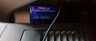
To use the connector, you need special equipment. The most common adapter is called ELM 327. It is small in size, easily connects to the connector, and then transmits data from the car’s memory via the Bluetooth interface. Using various programs, you can view the main parameters even from a smartphone (for example, using the Torque program).
This connector also includes an on-board computer and a scanner. With their help, error codes and various vehicle parameters are read. If during the diagnostics you have received error codes for some parameters, you should contact a specialist. The documentation should describe what exactly this error means.
Early Grant models did not have an engine temperature indicator on the dashboard. Therefore, the diagnostic connector was often used precisely to monitor this particular indicator. In general, it is most often used to display various engine parameters in digital form. Given the complexity of diagnostics, few car owners take it seriously.
Sometimes diagnostic connectors are used by car thieves. The fact is that the circuit provides a contact for monitoring the immobilizer. However, this method is used extremely rarely. If you still want to protect yourself from it, you should purchase a special circuit that distributes contacts differently. In this case, the hijacker will not be able to disable the protection.
Modification of the Lada Priora connector
Over a certain period, injection cars have progressed noticeably, and different variations of the ECU have been designed. At first, the system read the codes according to the indicator lamp, and in a special situation it flashed. The mechanic only had to indicate the rhythm on paper, and then, after checking it with the table, identify the error. After some time, special diagnostic devices were improved:
- PC adapters;
- car scanners.
Undoubtedly, one thing unites them: in order for the equipment to communicate with the ECU, a special connector is required. At first, these plugs were made differently in each car model (round, square, or holes paired for a probe). Meanwhile, manufacturers gradually began to think about unification. And already at the beginning of the 21st century, the well-known connector for OBD-2 diagnostics appeared.
Do-it-yourself diagnostics
Using the elm327 diagnostic device in android
Various breakdowns of sensors and other devices can cause increased gasoline consumption, incorrect engine operation, and increased wear of car system components. Despite the presence of errors, the VAZ Priora will drive until the driver has to make expensive repairs because of them.
VAZ Priora car
So that the motorist does not suddenly have to face the need for repairs, a special controller is installed on the VAZ Priora, with the help of which the driver can diagnose breakdowns. This can be done either using special additional equipment or an on-board computer installed in the car.
For example, you do not have a special tester, so we will look at diagnosing the vehicle for errors using the on-board computer. The BC is built into the dashboard and can be used to read combinations of faults. To do this, you need to activate the auto test mode.
The arrows on the dashboard move to maximum values when performing self-diagnosis of the vehicle
First, turn off the ignition. After this, hold down the daily mileage reset button and turn on the ignition
Please note: the button must be held down. There is an LCD indicator on the vehicle's dashboard, keep an eye on it. When you turn on the ignition, all icons will start to light up, and all arrows (speedometer, tachometer, antifreeze temperature sensor, gasoline level status) will begin to move to the maximum values and back
That is, if all the arrows behave as described here, this means that the sensors and indicators are functioning correctly. Now you need to find the button for switching BC functions - it is located on the right steering column switch. By clicking on it, the software version (1.0 and higher) will be displayed on the screen. Click on this button again. Combinations of faults will begin to appear on the screen. If necessary, you can reset error data here. To do this, press and hold the daily mileage reset button for about three seconds.
The appearance of a fault combination on the LCD screen during self-diagnosis
