Modification of the cylinder head of the VAZ 2109 8 valves
The car 2109 (injector), 1500 cubic meters volume, 8 valves was received for repair. After driving 100 tkm on gas fuel , the compression in cylinder 2 dropped ( 4 atm ). Diagnostics indicated a burnt valve. The owner of the car decided to repair the cylinder head (cylinder head) and install a DynaCAMS RS tuning camshaft, produced by OKB Dvigatel (Ufa) . RS54 for serial heads without modifications , with a lift of 10.6 mm . However, our experience in building such heads made it possible to offer the car owner a 2110-RS58 with an 11 mm . The car already had a 4.1 GP, and the characteristics of the Ufa camshafts gave reason to believe that the car would not lose traction at the bottom. They did not carry out a comprehensive modification of the cylinder head, because For the future, the car owner is focused on installing 16- valve head, and the budget was limited, but some improvements were still made, we’ll tell you in more detail later.
The cylinder head was removed. It turned out that the cylinder head gasket began to lose its seal between cylinders 2 and 3 - gases had already begun to “flow” under the gasket, after 100 tkm the head “moved” a little in the middle part - a common picture for a VAZ 8 valve. Corrected by milling the head plane. The reason for the drop in compression was also found - the exhaust valve plate of cylinder 2 was cracked.
The exhaust valve guide bushings were critically worn. The exhaust valves have a lot of play in their bushings. In addition, on the burnt-out valve, the seating belt with the oil scraper cap broke off from the guide bushing. All valve stem seals were stiff, and the wear on the valve stems was significant.
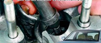
As a modification to the head, the internal diameters of the seats were increased. In practice, this is akin to installing larger valves. Boring of the seats allows you to increase the capacity of the seats, without expensive replacement of seats for large valves, while the dimensions of the valve plates remain as standard. The head channels remained as standard (without modification).
Additionally, work was carried out to change the lubrication scheme of the valve pushers. On the serial head 21083, the pushers are lubricated with oil from the bath (without pressure). We have developed a method for lubricating pushers with oil under pressure. In practice, this is expressed in a significant reduction in mechanical noise from the cylinder head ; the engine runs calmer and quieter, as with hydraulic pushers. The acoustic noise inside the car is noticeably reduced. Mechanical noise from the pushers is due to the gradual wear of the pusher wells and the “cups” themselves - at high mileage such noises cannot be eliminated in principle - there is only one way out - to change the head, because Repairing wells is difficult to implement in practice (high cost). Supplying oil under pressure into the wells reduces wear on cups and wells, as well as camshaft cams, because they receive additional lubrication. Oil under pressure creates an additional “cushion” in the “well-pusher” friction pair, selects gaps, thereby ensuring shock-free operation of the pusher. Of course, the engine is equipped with non-flat RS washers (modified from serial adjusting washers) . Supplying oil under pressure into the wells of the pushers is our know-how, it has been successfully mastered and used on Oka engines, 21102111. The complex system K-POWER lubrication of the pusher with oil under pressure and non-flat RS washers ( the OKB Engine patent ) allows the preparation an engine that runs quieter and more calmly, even compared to a new production engine.
Separately, I would like to say a few words about the components. We ordered valve guides from Moscow from Moscow from Kolbenshmidt (Germany) and valve stem seals from Goetze (Germany) especially for this cylinder head. Kolbenshmidt cast iron guides are the highest quality and longest lasting of all cast iron bushings available on the market. Compared to them, the VAZ or SM guides that have flooded the market are nothing more than a handicraft. Goetze valve stem seals - a recognized standard of quality, at one time they were even installed on the VAZ assembly line until they were replaced by “Reserve” caps. Camshaft oil seal – Victor Reinz (Germany). The timing and alternator belts were replaced with PowerGrip and Dayco . But the tension roller was left by Vologodsky, VBF . It is difficult to buy a high-quality roller (a normal Gates roller ordered from Moscow costs at least 400-500 rubles ), most rollers sold in stores have broken geometry and after installation they begin to wear out the timing belt. Factory VBFs XADO repair lubricant . Xado technology really works in a wide variety of bearings, as we have already repeatedly seen (but we do not recommend using XADO in gearboxes). After the roller is restored using Hado technology , the bearing play disappears, the noise decreases, and the roller works better and lasts longer than a new one. With the same success, Hado repair technology is used in generator bearings. On this machine, the generator was disassembled, the rear bearing was repaired using Hado technology, and the front bearing was replaced with a new one. The generator immediately “calmed down.”
, a DynaCAMS 2110-RS58 with an intake valve lift of 11 mm was installed . To ensure normal operation of the camshaft with such a lift in the serial cylinder head without breaking the valve springs, modified upper spring plates were used. The camshaft was specially ordered with a slightly reduced cam base, since the seats on the cylinder head sagged naturally due to the engine running on gas. , lightweight T-valves were installed . The valve disc profile with a recess allows to significantly reduce the weight of the valve compared to serial ones. A set of such valves allows the engine to breathe better at high speeds, increases engine power and throttle response. The cylinder head plane was milled. The compression ratio was slightly increased relative to the production engine.
It turned out that the car was equipped with one of the first versions of the ECU. The engine control unit was replaced on January 5, after which the “brain” was reflashed, taking into account the installation of a tuning camshaft. In addition, the engine was equipped with a GREEN . The gas equipment was removed from the vehicle. In addition, the car has a direct-flow muffler can.
Refinement of the cylinder head
When examining the cylinder head, we can see many shortcomings - these are what we will talk about, it was the engineers who did not allow the VAZ cylinder head to reveal the full potential, perhaps for the sake of increasing the resource, although in practice this does not happen...
1. Docking the channels of the cylinder head and manifolds
One of the manufacturers' shortcomings: inaccurate joining of the holes of the cylinder head channels and manifolds. We all know very well that when obstacles arise in the air flow, turbulence occurs; many mistakenly believe that the manifold needs to be polished to a mirror finish; for example, the intake manifold of the AUDI 100 has a so-called “Christmas tree” for a more thorough mixture of fuel and air. Therefore, we need to get rid of inaccuracies in the place where the parts are joined; at the same time, we need to check the gaskets under the manifolds so that they also do not create obstacles. It is advisable to place the collectors on pins before starting work. This is necessary for the reason that the fastening of the manifolds on VAZ cars allows for a slight displacement of the planes of the cylinder head and manifolds relative to each other, which can lead to a zero result. We find places on the cylinder head and manifolds (2 pins for each at the edges) for convenient drilling. We place the metal pins tightly in the cylinder head, but the manifolds should fit onto them easily, but without play. Make the necessary holes in the gasket. Now accurate positioning of the manifolds and cylinder head is ensured. It should be taken into account that if the diameter of the cylinder head channel is slightly larger (1-1.5 mm) than the diameter of the intake manifold channel, but their coaxiality is the same, then this can be neglected, since there is no significant resistance will not create. At the exhaust, a similar situation is created, only the cylinder head channel can now be slightly smaller than the exhaust manifold channel.
2. Inlet and outlet ports of the cylinder head.
If you carefully examine the intake/exhaust channels of the factory cylinder head, you will notice casting tides in the area of the valve guides, bushings protruding into the channel and, in places, the broken shape of the narrow channels. Using ball cutters of different shapes and sizes, it is necessary to increase the flow area of the channels and remove all irregularities and protruding parts. The shape of the channel must be changed so that its bend is as smooth as possible, but maintains certain radii of curvature. The inner surface of the intake channels is left slightly rough for better evaporation of gasoline from their walls. The exhaust channels can be polished, although this will not give a noticeable effect. The cross-section of the channel should not be a regular circle. The intake port is elliptical in shape with a slight barrel-shaped extension in front of the valve seat. The rest of the cylinder head channel and intake manifold gradually tapers in the direction of flow.
When increasing the diameter of channels, it is necessary to take into account nearby internal communications. If you work carelessly, you can damage the oil channel or the cooling jacket channel. When working with the cylinder head of eight-valve engines, which are used in front-wheel drive VAZs, you must be extremely careful. Although this will not save you when boring one intake channel, in which the oil channel runs so close that its opening is inevitable. Unfortunately, even if the channel remains unopened, it may simply be covered with a thin layer of aluminum and later break through under the oil pressure of a running engine. It is better to install steel or aluminum bushings after opening the channel, or weld the channel with argon.
First, decide whether to start boring from the manifold or cylinder head. With a significant increase in the diameter of the channels, work begins on parts with thinner walls, and then the channels of the mating blocks are bored according to their shape and position. In classic VAZ engines, it is customary to start boring from the manifold, because the cylinder head channels have sufficient thickness for subsequent alignment.
Note the parts of the valve guides that protrude into the channels. They create noticeable obstacles to the flow, so they try to shorten or sharpen them. Sometimes the bushings are ground flush with the wall of the channel and, although this better optimizes its throughput, such modification reduces the service life of the guides, which are already short on forced engines.
3. Cylinder head valves
Here the improvements are aimed at increasing the throughput and reducing the weight of the valves. The throughput can be increased by changing the profile of the plate, as well as the working and additional chamfers of the valve. When regrinding valves, excess metal is removed from both sides of the valve plate. A small notch is made on the front side, and on the back side the radius of the transition of the rod into the plate is reduced. The plate and valve stem are also made thinner. If you do not plan to change the bushings, then remove the excess metal from the valve stem from the poppet to the guide bushing.
Reducing the diameter of the entire leg will require replacing guide bushings with a smaller hole diameter. On 8-valve VAZ engines, by reducing the diameter of the valve stem from 8 to 7 mm, you can achieve a reduction in the weight of the rod by 23.5%. For 16-valve engines, the core diameter is initially 7 mm. You can supply titanium-aluminum valves, which are 40% lighter than steel, but they are very fragile and expensive. In this case, the seats have to be replaced with bronze ones, which are softer compared to cast iron, which leads to a decrease in valve rebound when closing and additionally dampens shock loads.
On 8-valve VAZ engines, the working chamfers are made narrower, the exhaust angle is changed to 45º, and the intake angle to 30º. In the places where the valve plate transitions into the working chamfer, additional chamfers are cut, which gives an increase of about 5-6%.
Further refinement involves replacing the valves with larger models. They can be installed without replacing seats, since the standard ones allow you to slightly increase their internal diameter and the diameter of the working chamfer. This is practiced on 16-valve cylinder heads 2112, on which lightweight, enlarged valves 32/27 “Ae” VAZ 2112 / VAZ 2172 Priora 16V are installed.
It is also possible to install larger valves, which involves replacing the seats. In this case, the original saddles are cut out and larger cast iron or bronze ones are installed. The necessary chamfers are cut into them and valves of an even larger size than those previously discussed are installed. This method is more expensive than the first, but the most effective, and for 8-valve cylinder heads of VAZ cars it is the only solution. The increase in power with this modification reaches 8-10%. In this case, you can install lightweight, enlarged valves 39/34 “STK Motor Sport” VAZ 2108 / 2110 8V.
Data on valves that can be installed on VAZ engines:
- — VAZ 2101-2107, 21213 — valves from 39/34 to 42/35;
- — VAZ 21083/2111 – valves from 39/34 to 40/34;
- — VAZ 2112 – valves from 31/27 to 33/29,
where the numerator indicates the diameter of the intake valve plates, and the denominator indicates the diameter of the exhaust valves.
Of course, this is not the only solution, and you can select the sizes of the valve plates yourself, but you must take into account that for naturally aspirated engines, the optimal ratio of the exhaust valve area to the intake valve is ¾ or approximately 75%. This is clearly seen from the following data:
31/27 - 75.9% 33/29 - 77.2% 39/34 - 76.0% 40/34 - 72.3% 41/35 - 72.9% If your car is supercharged or nitrous oxide-injected, it will need larger exhaust valves because the engine produces more exhaust gases. For such engines, the valve ratio can be 90% or more.
4. Cylinder head valve springs.
Standard springs are calculated for a specific engine using a serial camshaft. A sufficient safety margin is taken into account, designed for relatively low speeds. In classic engines, valves hang at speeds of more than 7000, on the VAZ 21083 higher speeds are allowed, and on the VAZ 2112, poor valve operation is likely at speeds of 7500-8000 rpm.
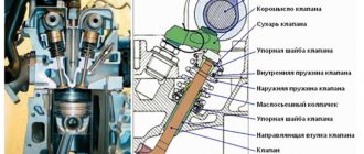
Replacing the camshaft with a higher camshaft can lead to stuck valves. The simplest way is to increase the preload of the standard spring, which is done by placing a washer under it. The force on the spring increases, but the free play decreases noticeably.
When installing sports camshafts, more stringent requirements are imposed on the forces on the springs. In this case, a large cam lift and a corresponding spring stroke are required, so they are replaced with stiffer ones that have a larger compression stroke. A good example is the reinforced valve springs PROSPORT VAZ 2108 / 2110 8V. Stiffer springs noticeably increase the load on the valves, camshaft and discs, so it is advisable to carry out such modification as the last of all methods of increasing the valve sticking threshold.
Another way is to lighten the valve spring retainers. Their lighter weight reduces the load on the camshaft and timing parts, which is especially important at high speeds. You can resharpen the standard plates, but it is better to install new ones made of aluminum alloy or titanium. Aluminum ones are cheaper, but are subject to deformation in critical operating conditions. Titanium products are more durable, although some car enthusiasts are deterred by their price.
5. Cylinder head valve lifters
In VAZ 2108 and 2112 engines, the kinetic connection of the cylinder head valves with the camshafts is carried out using pushers. On the cylinder head 2108 they are mechanical with adjusting washers, and on the cylinder head 2112 they are hydraulic compensators. For 16-valve engines, solid valve tappets d-30 mm SPORT VAZ 2112/2172/1118 16V are suitable. Standard pushrods have some limitations and are therefore unacceptable when working with sports camshafts. In this case, solid mechanical pushers are used, which have an increased diameter and do not require adjusting washers. To install them, it is necessary to bore the wells of serial pushers to the required size. The valves are regulated by selecting thrust bearings of the required size, which is quite labor-intensive.
6. Cylinder head valve levers
On classic VAZ engines, the valves are driven from the camshaft by levers (rockers). They are convenient and easy to adjust valve thermal clearances and allow the use of compact camshafts, but they are excessively massive and allow some deviation in the kinematics of valve movement. Also, on the “classic” cylinder head, the rocker can fly off its seat at extremely high speeds. To combat these shortcomings, the levers are lightened, light-alloy models are installed and placed on stiffer springs.
7. Cylinder head valve guides
Depending on the type of engine and expected operating modes, the design and material of the valve guides are selected. Reasons that may require modification or replacement of standard equipment:
- — When using valves with a smaller stem diameter;
- — When the part of the guide bushing protrudes strongly into the cylinder head channel;
- — If the shape or size of the opposite part of the guide does not meet the requirements;
- — If the thermal conductivity of the guide bushing is insufficient (replacement with bronze ones is possible).
Bronze is a good heat conductor, it removes heat well from the valve and effectively dissipates it into the cylinder head, therefore, on highly accelerated engines, the use of bronze guide bushings is extremely necessary. They have a slightly shorter service life compared to metal-ceramic products, but it all depends on the operating modes of the engine and their manufacturer.
8. Shape of the cylinder head combustion chamber
With this modification, you can significantly reduce the risk of detonation, improve cylinder filling and create conditions under which the fuel mixture will be better distributed, mixed and ignited.
Detonation occurs in places farthest from the spark plug. This is explained by the fact that when the mixture ignites, the pressure in the combustion chamber increases sharply and leads to extreme compression of the mixture that has not yet ignited. This provokes its self-ignition, which is explosive in nature and leads to a sharp increase in temperature and pressure in the cylinder. Detonation occurs, characterized by metallic sounds and propagating through the engine in a series of shock waves of detonation explosions. Frequent occurrences of detonation lead to devastating consequences, so measures must be taken to eliminate them. To do this, the sharp edges and corners of the combustion chambers are smoothed out as much as possible, casting errors are removed and the surface of the combustion chambers is polished, which additionally adds 5% of power by reducing heat losses.
To improve cylinder filling and create optimal conditions for the fuel mixture, it is necessary, first of all, to pay attention to the shape of the combustion chamber around the valves. On VAZ 8-valve cylinder heads, the combustion chamber is wedge-shaped and the valve gap is “screened” by its steep walls. This leads to the fact that the flow of the working mixture is forced to overcome additional obstacles, which is clearly noticeable when installing larger valves. Therefore, the volume of the combustion chamber must be expanded around the valve. It is also necessary to modify the valve gap segment near the spark plug and make the connection between the bottom and vertical walls of the combustion chamber smoother. There should be no steps or wells around the valve seats, and the conical recess of the valve seat should be no more than 30º relative to the bottom of the combustion chamber.
The VAZ 2112 cylinder head initially has a hemispherical combustion chamber, which minimizes all necessary modifications and eliminates the flaws of mass production.
9. Compression ratio in the cylinder block
The compression ratio is the ratio of the total volume of the cylinder to the entire volume of the combustion chamber. The more compressed the fuel mixture is before ignition, the more work it will do subsequently. By increasing the compression ratio, we increase engine power, but there are also limiting factors, such as an increase in the load on the piston and the risk of detonation. Standard cast pistons of VAZ engines allow a compression ratio of up to 11:1.
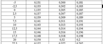
For engines with small timing timing, the increase in power relative to the increase in compression ratio is well monitored in the table.
The most noticeable positive effect of increasing the compression ratio is in engines with wide valve opening phases. This occurs because the filling coefficient of naturally aspirated VAZ engines does not exceed 100%, that is, the dynamic compression ratio does not exceed the static compression ratio. Dynamic compression ratio is the volume of the fuel-air mixture entering the cylinder relative to the volume of the combustion chamber. When using wide-phase camshafts at low and medium speeds, the dynamic compression ratio is lower than the static one. An increase in the compression ratio leads to a proportional increase in the dynamic ratio, which has a positive effect on the power and economic performance of the engine. In this case, it is necessary to eliminate the prerequisites for the occurrence of detonation at the maximum cylinder filling ratio, which is achieved by increasing the octane number of the fuel and changing the composition of the fuel-air mixture.
As engine speed increases, the duration of the combustion cycle decreases, which can lead to incomplete combustion of fuel and, consequently, loss of power. Therefore, by increasing the compression ratio, we speed up the combustion process, which allows us to get maximum power from the engine.


