Mounting block
Lada Vesta fuse diagram
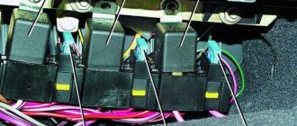
Interior mounting block
Schematic location of fuses
Body connector
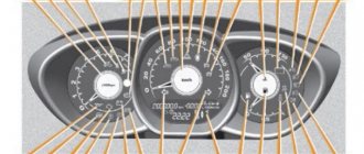
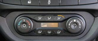
Layout of buttons on the steering wheel
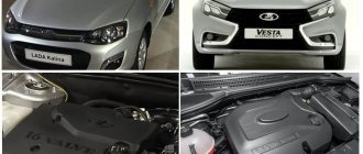
Lada Vesta is equipped with many electrical appliances, each of which is vulnerable to voltage surges. To protect consumers, there is a fuse in the circuit of each of them, and if for some reason it blows, it will have to be replaced, otherwise the electrical appliance will not work. Just first you need to find the Lada Vesta fuse box.
Why are fuses needed?
Fuses are elements of an electrical circuit that protect devices from voltage surges. They consist of a plastic case, two contacts and a working element.
The principle of their operation is simple: each element has an operating voltage, and if this value is exceeded, it will immediately burn out and the circuit will open. In fact, the protective component takes the blow, protecting electrical appliances from damage. Its purchase is much cheaper than replacing one or more consumers, which, among other things, can affect the control of the car.
Interesting!
The cigarette lighter in Lada Vesta has a fuse that blows more often than others. Usually the reason for this is connecting devices with high current consumption or several devices at once through a tee.
Mounting block Lada Vesta in the car interior
The location of this mounting block is quite familiar for most modern cars - near the driver’s left foot. In order to gain access to this unit, you need to unscrew the cover fastening handles, remove the lock on the upper right side of the cover and pull the cover down. The mounting block itself also has a cover that can be removed by disconnecting the upper holders.
| № | Denomination | Chain | Purpose | Type |
| 1 | 15A | K15R | Power supply for the right steering column switch (washer) | mini |
| 2 | 30A/5A | K15R | Left steering column switch (not lux/lux) | mini |
| 3 | 10A | Left high beam headlight, (not luxury) | mini | |
| 4 | 30A/5A | K30S | Left steering column switch (not lux/lux) | mini |
| 5 | 15A | K15R | Seat heating | mini |
| 6 | 7.5A | K30S | Side lights on the starboard side | mini |
| 7 | 10A | K30S | Left side marker lights | mini |
| 8 | 5A | K30S | Rear fog lights | mini |
| 9 | BEHIND | Right turn signal in the mirror | mini | |
| 10 | 5A | K15S | AMT robotic gearbox selector | mini |
| 11 | 10A | Left low beam headlight (not lux) | mini | |
| 12 | 15A | K30S | BCM controller (direction indicators) | mini |
| 13 | 10A | K30S | VSM controller (own power supply) | mini |
| 14 | 10A | K30S | Turning off the brake pedal | mini |
| 15 | 5A | VTR | Power supply for rain and light sensor, headlight range control | mini |
| 16 | 5A | VTR | Turning off the brake pedal | mini |
| 17 | 5A | VTR | Lighting for the glove compartment, trunk, sills | mini |
| 18 | BEHIND | Left turn signal in the mirror | mini | |
| 19 | 10A | Right low beam headlight (not lux) | mini | |
| 20 | 5A | Heated exterior mirrors | mini | |
| 21 | 15A | K15S | Airbag system control unit | mini |
| 22 | 5A | K15S | Instrument cluster | mini |
| 23 | 5A | K30S | Instrument cluster | mini |
| 24 | 5A | ACC | ERA GLONASS, radio | mini |
| 25 | 5A | VTR | ESP 9.1 controller | mini |
| 26 | 15A | K30S | Power supply to fuel pump module | mini |
| 27 | 5A | K15S | Power supply for parking sensors | mini |
| 28 | 5A | K15S | Electric Power Steering Controller | mini |
| 29 | 10A | K30S | Power supply for trailer lighting | mini |
| 30 | 5A | K15S | ERA GLONASS controller | mini |
| 31 | 5A | K30S | ERA GLONASS controller | mini |
| 32 | 10A | K15S | Power supply for K15M bus (engine compartment) | mini |
| 33 | 5A | VTR | Window control | mini |
| 34 | 5A | VTR | Power supply for steering angle sensor, steering wheel button block | mini |
| 35 | 5A | VTR | Driver's door switch block | mini |
| 36 | 15A | K30S | Radio, diagnostic connector | mini |
| 37 | 7.5A | K30S | Right brake light | mini |
| 38 | 7.5A | K30S | Left brake light | mini |
| 39 | 10A | K15R | Daytime running lights (not luxury) | mini |
| 40 | 10A | K15R | Right high beam headlight (not luxury) | mini |
| 41 | 20A | ACC | 12V socket (power supply for additional devices), cigarette lighter | JCase |
| 42 | 20A | K30S | VSM controller (VTR bus power supply) | JCase |
| 43 | 20A | K30S | BCM controller (door locks) | JCase |
| 44 | 30A | K30S | Window lifters | JCase |
| 45 | 30A | K30S | Interior heater fan | JCase |
| 46 | 30A | K15R | Power supply for the right steering column switch (windshield wiper) | JCase |
| 47 | 25A | K30S | EMM controller (PDS, LBS, LGO) | auto |
| 48 | 30A | K30S | EMM controller (windshield wiper) | auto |
| 49 | 25A | K30S | EMM controller (PTF, ZPTO, license plate) | auto |
| 50 | 25A | K30S | EMM controller (LDS, PBS, PGO) | auto |
| Relay | Denomination | Chain | Purpose | |
| K1 | 70/50A | K15R | Power supply for lighting and seat heating (not luxury/luxury) | |
| K2 | 30A | Free | ||
| K3 | 30A | Heated rear window | ||
| K4 | 30A | Front windows | ||
| K5 | 40A | Interior heater fan | ||
| K6 | 30A | Rear window lifter | ||
| K7 | 20A | Fuel pump module | ||
| K8 | 20A | ACC (12V socket power supply) | ||
Lada Vesta fuse box with description (engine compartment
The required box is located above the battery, on the right side of the air filter. On the cover of the unit you can see warning signs in the form of a crossed out figure of a man with a hose and a lightning bolt.
To remove the cover, bend the two latches at the top and bottom. Be careful because... they are very fragile.
Schematic layout
The contents of this mounting block are as follows:
Mounting block
The current limit (amps) is indicated on each component. The Lada Vesta fuse diagram under the hood looks like this:
Lada Vesta fuse diagram
Which circuit each fuse belongs to and which consumer it is responsible for can be found in the table below.
Fuse Circuit Chart Fuse Chart Note: Depending on the configuration, some items may not be present.
Table with the designations of the relays that are present in the engine compartment block:
Relay designation table
Lada Vesta relay and fuse diagram
The solution to any problem related to the electrical equipment of a car begins with checking the fuses. They, together with the relay, are located in the mounting blocks (fuse box and black box) of the passenger compartment or engine compartment.
The lists contain a complete set of fuses and relays, taking into account all vehicle configurations. In simpler versions, individual relays and fuses from this set may not be used.
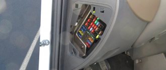
Lada Vesta fuse box with description (interior)
This mounting block is located in a place familiar to drivers - near the left foot. Actually, the space around the trunk opening button and the headlight adjustment control is the cover of the mounting block.
First, remove the plastic clips (nails) that secure the cover to the upholstery. One of them is located on the side of the ignition switch, the other is in the lower left part of the cover (may be absent on some cars). Next, turn the 3 plastic handles at the bottom and pull the lid, releasing all the holders.
Schematic layout
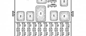
In the interior mounting block you will see the following picture:
Interior mounting block
On a note!
In the lower right corner there are spare fuses for the Lada Vesta.
Schematically the block looks like this:
Schematic arrangement of fuses It is deciphered as follows: Explanation of spare fuses Explanation of spare fuses Explanation of spare fuses Explanation of spare fuses Explanation of spare fuses Relays that are present in the cabin: Designations of the snout in the cabin Body connector Diagram of the buttons on the steering wheel
Fuse and relay box in the interior of Lada Vesta
The block is located in the usual place, on the left side of the instrument panel near the driver’s foot.
To gain access to the relays and fuses in the Lada Vesta interior you need:
- turn the plastic handles (3 pieces) holding the unit cover from below;
- remove the lock in the upper right part of the cover;
- pull the bottom of the cover, disconnect its upper holders to the instrument panel and remove the unit cover.
Fuse and relay diagram in the Lada Vesta interior
Description of fuses
| № | Denomination | Purpose |
| F1 | 15A | Power steering column switch right, washer |
| F2 | 30A/5A | left steering column switch, non-lux/lux |
| F3 | 10A | left high beam headlight, not luxury |
| F4 | 30A/5A | not luxury/luxury |
| F5 | 15A | Seat heating |
| F6 | 7.5A | side lights right |
| F7 | 10A | side lights left |
| F8 | 5A | rear fog lights |
| F9 | BEHIND | right direction indicator in the mirror |
| F10 | 5A | AMT robotic gearbox selector |
| F11 | 10A | left low beam headlight (not luxury) |
| F12 | 15A | BCM Controller (Turn Signals) |
| F13 | 10A | BCM controller (self-powered) |
| F14 | 10A | Turning off the brake pedal |
| F15 | 5A | Power supply for rain and light sensor, headlight range control |
| F16 | 5A | Turning off the brake pedal |
| F17 | 5A | Lighting for the glove compartment, trunk, sills |
| F18 | 3A | left indicator in the mirror |
| F19 | 10A | low beam headlight right (not luxury) |
| F20 | 5A | Heated exterior mirrors |
| F21 | 15A | BU SNPB |
| F22 | 5A | instrument cluster |
| F23 | 5A | instrument cluster |
| F24 | 5A | ERA GLONASS, radio |
| F25 | 5A | ESP9.1 controller |
| F26 | 15A | Power supply to fuel pump module |
| F27 | 5A | Power supply for parking sensors |
| F28 | 5A | EURU controller (electric power steering) |
| F29 | 10A | Power supply for trailer lighting |
| F30 | 5A | ERA GLONASS controller |
| F31 | 5A | ERA GLONASS controller |
| F32 | 10A | K15M Bus Power (Engine Compartment) |
| F33 | 5A | Window control |
| F34 | 5A | Power supply for steering angle sensor, steering wheel button block |
| F35 | 5A | Driver's door switch block |
| F36 | 15A | Radio, diagnostic connector |
| F37 | 7.5A | stop lamps right |
| F38 | 7.5A | stop lamps left |
| F39 | 10A | daytime running lights not luxury |
| F40 | 10A | right high beam headlight (not luxury) |
| F41 | 20A | 12V socket (power supply for additional devices), cigarette lighter fuse for Lada Vesta |
| F42 | 20A | BCM controller (VTR bus power supply) |
| F43 | 20A | BCM Controller (Door Locks) |
| F44 | 30A | Window lifters |
| F45 | 30A | Interior heater fan |
| F46 | 30A | windshield wiper (switch power) |
| F47 | 25A | EMM controller (PDS, lBS, lGO) |
| F48 | 30A | EMM controller (windshield wiper) |
| F49 | 25A | EMM controller (PTF, ZPTO, license plate) |
| F50 | 25A | EMM controller (lDS, PBS, PGO) |
Description of the relay in the block under the Vesta instrument panel
| Relay | Denomination | Purpose |
| K1 | 70/50A | Power supply for lighting and seat heating (not luxury/luxury) |
| K2 | 30A | Free |
| K3 | 30A | Heated rear window |
| K4 | 30A | Front windows |
| K5 | 40A | Interior heater fan |
| K6 | 30A | Rear window lifter |
| K7 | 20A | Fuel pump module |
| K8 | 20A | ACC (12V socket power supply) |
Replacing the fuse
In one of the tables, find a device that has stopped working - next to it there will be a designation of a supposedly burnt-out element. At the same time, you will understand where the fuse box is located.
Open the block cover, find and remove the problematic fuse, following the diagrams. The same algorithm applies to a failed relay.
If the contact inside is broken, it means it has burned out. However, this is not always noticeable, so it is better to do a continuity test with a tester.
Important!
Before replacing, be sure to find out the cause of the burnout.
The new protective component must match all the characteristics of the old one: the same format, color and current limit designation.
Addition from car owners
Additional information about fuses and relays is provided by unnown:
Show/Hide text
In Table 1, the data of the original relays is highlighted in color. I tried to collect the main characteristics (min required) of possible relay analogues, similar in size, design and characteristics. Where there are empty cells in the table, there is no data. Equivalent R is the actual measurement from the relay contacts. Of course, my data is not a panacea for all ills. Data collected from manufacturers' sources (data sheet) and from online store catalogs.
Before replacing a fuse, you must first determine the cause of its blown. The manufacturer does not allow the use of fuses that differ in current rating from those recommended in the tables below. This can lead to malfunctions in the operation of Vesta's electrical equipment, short circuits and even a car fire!
Attention!
The relay and fuse diagram may differ depending on the configuration and production date of the vehicle. Current diagrams of the mounting block are presented in the operating manual for the date of manufacture of the car (download from the official website for a sedan or station wagon).
Let us remind you that you can quickly find the necessary material through the contents of Lada Vesta.
Categories of products that may be of interest to you based on the article “Lada Vesta relay and fuse diagram”:
No entries found.
Products from the Dustershop77 range on the topic of the article:
| Image | vendor code | Name | Manufacturer | Price | Availability | Add to cart |
How to open the fuse box
Unlike Grant Kalin and Prior, in order to open the mounting block in the cabin, you need to perform a number of actions that are unfamiliar to the owners of previous models.
The fuse block plug is held on by plastic “nails” of the pistons. All you need to do is pull the head of the plastic black nail towards you, leaving the washer behind.
Some people have 2 of these studs, others have 1, depending on the time the car was produced, because... Over time, all elements are modernized.
Next, remove the latch at the top of the plug on the ignition switch side and pull the bottom of the cover, thereby opening the fuse box in front of you. If necessary, disconnect the connectors of the trunk release and headlight adjustment buttons.
To put the cover back in place, perform the steps in reverse order.
Removing the cover of the fuse box under the hood is much easier and it is unlikely that anyone will have any questions about it.
1 - fuse box cover (in this case, the stud is located only on the side of the ignition switch, in others the second stud is located in the lower left corner on the block cover)
3 — adjusting the electric headlight leveler
4 — trunk lid opening button
Fuse box in the engine compartment
The engine compartment fuse box is located above the battery, to the right of the air filter. The block can be unmistakably identified using a special sign on its cover (a person and a zipper), which must be opened with extreme caution due to the unreliability and fragility of the upper and lower fixing elements.
Fuse diagram in the engine compartment of Lada Vesta
Each of the elements contains information about the maximum current strength, measured in amperes, and corresponds to a particular color.
Engine compartment relay diagram
Replacing the fuse box for Lada Vesta SV Cross
Necessary tools, materials:
- rags;
- additional lighting as needed;
- a set of new relays;
- plastic clips in the amount of 3 - 5 pieces, in case the standard ones are damaged.
Sequence of actions when replacing the power supply in the engine compartment:
- The car is installed within the perimeter of the repair area, the hood is open, and the parking brake is depressed.
- Behind the battery, closer to the air filter housing, a module with fuses is installed. We unclip the side latches and remove the relay with the serial number we need.
- We troubleshoot the power supply, clean the internal contents from dust and dirt.
- We install a new “relay” and assemble the structure in the reverse order.
Algorithm of actions when replacing inside the car:
- We turn off the engine and lock the parking brake.
- In the lower left part of the dashboard, behind the steering rack, we find the power supply cover, snap off the four plastic clips.
- We remove the cover, unscrew the three latches, and lift the power supply towards you.
- We inspect the module, replace non-working “relays” with new ones, and assemble the structure in the reverse order.
Note to the driver! The detailed process of diagnosing and replacing the power supply is described in the article:. If desired, read the recommendations of specialists.
Fuse box in the passenger compartment
The location of this mounting block is the space between the trunk door release button and the driver’s left foot.
The unit cover is attached to the upholstery with special latches, which must be removed before opening it. Then you need to turn the 3 plastic handles that hold the lid, remove the lock from the upper right part and carefully pull the bottom of the lid towards you. After the above manipulations, the cover should be easily removed without much effort on the part of the owner.