What are the VAZ 2110 fuse box relays responsible for?
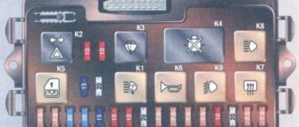
K1 – relay for monitoring the health of light bulbs; K2 – front wiper relay; K3 – repeater and alarm relay; K4 – low beam relay; K5 – high beam relay; K6 – additional relay; K7 – relay for turning on the heated rear window; K8 – backup relay (not installed on 110 series vehicles);
F1-F20 in the diagram are fuses. The circuits in the car are protected by fuses based on a certain rated current (in A). The battery charging circuit, generator circuit, ignition and engine starting are exceptions.
To replace a faulty fuse, first find the one that has blown, then eliminate the reason why it was damaged and then install a new one. Below is a list of fuses and information on each one.
* Never replace fuses with jumpers, this can lead to failure of various components and elements, including failure of the wiring tracks in the fuse box and even a car fire.
Where are the fuses located and how do I replace a blown fuse?
When something goes wrong with electrical appliances or the car's lights, then it's time to check the fuse box and find the right fuse in it to see and, most often, make sure that it is the cause. It so happens that most often problems with non-functioning electronics in a car arise precisely because of a blown fuse. However, the blown fuse itself can also indicate deeper problems of various kinds, which may need to be diagnosed if this continues to occur. So, where can you find fuses in different makes and models of cars?
There are actually three types of car fuses:
- ceramic,
- glass tubes
- flat.
If your car was manufactured earlier than, say, 1980 or a little later, then you most likely have fuses in the form of ceramic tubes. Glass tubes are another obsolete type of fuse that is also quite rare today. And the third type - in the form of a flat block - will most likely be in your car. Flat fuses are connected to the panel board by simply being inserted into it. Now let's move on to the main question: where are the fuses and how do we find them in the car?
What are the fuses on the VAZ-2110 responsible for?
Decoding fuses.
License plate lamps. Instrument lighting lamps. Side light indicator lamp. Trunk light. Left side marker lamps
Left headlight (low beam)
Left headlight (high beam)
Right fog lamp
Door window motors
Portable lamp (socket)
Engine cooling fan electric motor. Sound signal
Rear window heating element. Relay (contacts) for turning on the heated rear window
Recirculation valve*. Windshield and headlight cleaners and washers ( wiper fuse ). Relay (coil) for turning on the rear window heating
Starboard side marker lamps
Right headlight (low beam)
Right headlight (high beam). High beam warning lamp
Left fog lamp
Electrically heated seats. Trunk lock lock
Relay-breaker for direction indicators and hazard warning lights (in hazard warning mode). Hazard warning lamp
Interior lighting lamp. Individual backlight lamp. Ignition switch illumination lamp. Brake light bulbs. Clock (or trip computer)
Glove box lighting lamp. Heater controller ( heater fuse ). Cigarette lighter fuse for VAZ 2110, VAZ 2111, VAZ 2112.
Locking door locks. Relay for monitoring the health of brake light lamps and side lights. Direction indicators with warning lamps. Reversing lamps. Generator excitation winding. On-board control system display unit*. Instrument cluster. Clock (or trip computer)
Rear fog lamps
Table of external connections and connectors of the VAZ-2110 mounting block.
| Block | № | Color | Electrical circuits |
| Ш1 | 1 | ZhCh | fog lamp (left) |
| 2 | GP | trunk lock motor, heated seats | |
| 3 | R | door lock relay | |
| 4 | ABOUT | power window relay | |
| 5 | ZhP | fog light relay | |
| 6 | AND | fog lamp (right) | |
| 7 | MS | power window relay | |
| 8 | — | reserve | |
| Ш2 | 1 | — | reserve |
| 2 | — | reserve | |
| 3 | — | reserve | |
| 4 | H | weight " - " | |
| 5 | ZhP | size (left rear) | |
| 6 | Warhead | outdoor light switch | |
| 7 | — | reserve | |
| 8 | ZhCh | license plate lamps, off instrument lighting | |
| 9 | KP | size (right rear) | |
| 10 | TO | size (right) | |
| 11 | ZhG | email windshield wiper motor, windshield wiper and washer switch. | |
| 12 | Z | outdoor light switch | |
| 13 | ABOUT | fog light switch | |
| 14 | Emergency | hazard switch | |
| 15 | — | reserve | |
| 16 | GP | Ignition switch (terminal 15), steering column switch | |
| 17 | R | windshield wiper and washer switch | |
| 18 | JV | steering column headlight switch | |
| 19 | — | reserve | |
| 20 | — | reserve | |
| 21 | AND | size (left) | |
| Ш3 | 1 | midrange | low beam (left headlight) |
| 2 | — | reserve | |
| 3 | WITH | low beam (right headlight) | |
| 4 | R | generator (cl. 30) | |
| 5 | TO | generator (cl. 30) | |
| 6 | TO | generator (cl. 30) | |
| Ш4 | 1 | PZ | on-board display system |
| 2 | GO | hazard switch | |
| 3 | IF | hazard switch | |
| 4 | H | weight " - " | |
| 5 | PG | portable lamp plug | |
| 6 | Salary | heated rear window switch, heated rear window lamp | |
| 7 | — | reserve | |
| 8 | — | reserve | |
| 9 | — | reserve | |
| 10 | ZhZ | steering column washer and windshield wiper switch | |
| 11 | B | email windshield wiper motor | |
| 12 | BW | steering column washer and windshield wiper switch | |
| 13 | GB | steering column switch, ignition switch lamp | |
| 14 | BP | brake lights, clock, interior lamp | |
| 15 | P | brake lights | |
| 16 | RP | off brake lights | |
| 17 | ABOUT | generator (cl. 30) | |
| Ш5 | 1 | AF | high beam (left lamp) |
| 2 | JV | rear window heating element | |
| 3 | G | heater controller, glove compartment lamp | |
| 4 | Z | high beam (right lamp) | |
| 5 | ZhG | Windshield wiper motor, SAUO recirculation valve | |
| 6 | PB | email cooling fan, beep |
Circuits protected by additional fuses (all fuses are 15 A) on the VAZ-2110:
Additional fuses: 1 – ignition module, controller; 2 – canister purge valve, vehicle speed sensor, oxygen (heating) sensor, air flow sensor; 3 – fuel pump relay, fuel pump, injectors.
Additional relays: 4 – electric fan relay; 5 – electric fuel pump relay; 6 – main relay (ignition relay).
There is a fog lamp fuse installed in the niche of the instrument panel behind the mounting block:
Lada 2111 Agneska › Logbook › relays and fuses
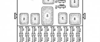
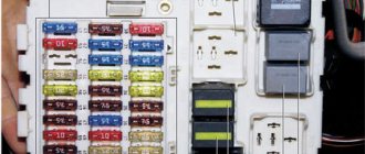
The main fuses and relays on the VAZ-2110, 21102, 21103, 2112 are located on the left side of the steering wheel, just below. The figure shows the designations on the fuse mounting block/
Fuse number Current strength, A Circuits protected by fuse F1 5 Lamps for license plate lights. Instrument lighting lamps. Side light indicator lamp. Trunk light. Left side side light lamps F2 7.5 Left headlight (low beam) F3 10 Left headlight (high beam) F4 10 Right fog lamp F5 30 Door window electric motors F6 15 Portable lamp F7 20 Engine cooling fan electric motor. Sound signal F8 20 Rear window heating element. Relay (contacts) for turning on the heated rear window F9 20 Recirculation valve. Windshield and headlight cleaners and washers. Relay (winding) for turning on the heated rear window F10 20 Reserve F11 5 Side light bulbs on the right side F12 7.5 Right headlight (low beam) F13 10 Right headlight (high beam). Indicator lamp for turning on the high beam. F14 10 Left fog lamp F15 20 Electric seat heating. Trunk lock lock F16 10 Relay-interrupter for direction indicators and hazard warning lights (in hazard warning mode). Hazard warning lamp F17 7.5 Interior lighting lamp. Individual backlight lamp. Ignition switch illumination lamp. Brake light bulbs. Clock (or trip computer) F18 25 Glove box lighting lamp. Heater controller. Cigarette lighter F19 10 Door locking. Relay for monitoring the health of brake light lamps and side lights. Direction indicators with warning lamps. Reversing lamps. Generator excitation winding. On-board control system display unit. Instrument cluster. Clock (or trip computer) F20 7.5 Rear fog lamps
Fuses and relays VAZ 2110, 2111, 2112
Cars with an injector and a carburetor were considered: 8 valves, 16 valves
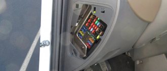
The relay and fuse mounting block for VAZ 2110, VAZ 2111, VAZ 2112 is located on the left side of the steering column in the instrument panel (to get to it, press the latch switch and lower the block down).
Layout of fuses and relays in the block (types of blocks installed on VAZ 2110, VAZ 2111, VAZ 2112 )
Mounting block 2110-3722010
Mounting block 2110-3722010-01
Mounting block 2110-3722010-08
Location of relays and fuses in the mounting block of VAZ 2110, VAZ 2111, VAZ 2112:
| Relay/fuse no. | Decoding |
| K1 | Lamp health monitoring relay |
| K2 | Windshield wiper relay |
| K3 | Relay-breaker for direction indicators and hazard warning lights |
| K4 | Low beam relay |
| K5 | High beam relay |
| K6 | Additional relay |
| K7 | Heated rear window relay |
| K8 | Fog light relay |
| F1-F20 | Fuses |
Explanation of fuses:
| Number | Current strength, A | Description of fuses |
| F1 | 5 | License plate lamps. Instrument lighting lamps. Side light indicator lamp. Trunk light. Left side marker lamps |
| F2 | 7,5 | Left headlight (low beam) |
| F3 | 10 | Left headlight (high beam) |
| F4 | 10 | Right fog lamp |
| F5 | 30 | Door window motors |
| F6 | 15 | Portable lamp (socket) |
| F7 | 20 | Engine cooling fan electric motor. Sound signal |
| F8 | 20 | Rear window heating element. Relay (contacts) for turning on the heated rear window |
| F9 | 20 | Recirculation valve*. Windshield and headlight cleaners and washers (wiper protection). Relay (coil) for turning on the rear window heating |
| F10 | 20 | Spare |
| F11 | 5 | Starboard side marker lamps |
| F12 | 7,5 | Right headlight (low beam) |
| F13 | 10 | Right headlight (high beam). High beam warning lamp |
| F14 | 10 | Left fog lamp |
| F15 | 20 | Electrically heated seats. Trunk lock lock |
| F16 | 10 | Relay-breaker for direction indicators and hazard warning lights (in hazard warning mode). Hazard warning lamp |
| F17 | 7,5 | Interior lighting lamp. Individual backlight lamp. Ignition switch illumination lamp. Brake light bulbs. Clock (or trip computer) |
| F18 | 25 | Glove box lighting lamp. Heater controller (heater fuse). Cigarette lighter fuse for VAZ 2110, VAZ 2111, VAZ 2112. |
| F19 | 10 | Locking door locks. Relay for monitoring the health of brake light lamps and side lights. Direction indicators with warning lamps. Reversing lamps. Generator excitation winding. On-board control system display unit*. Instrument cluster. Clock (or trip computer) |
| F20 | 7,5 | Rear fog lamps |
*In the car interior, in the very niche of the dashboard behind the mounting block, there is a fog lamp fuse .
**The central locking fuse is located behind the fuse box in a plastic box.
*** Additional relays and fuses are located in the passenger compartment on the right side of the instrument panel behind the side trim, attached with two screws.
All additional fuses are 15 A
| Relay/fuse no. | Decoding |
| 1 | Ignition module, controller |
| 2 | Canister purge valve, vehicle speed sensor, oxygen concentration (heating) sensor, air flow sensor |
| 3 | Fuel pump relay, fuel pump fuse, injectors |
| 4 | Electric fan relay (additional relay) |
| 5 | Fuel pump relay (additional relay) |
| 6 | Main relay (ignition relay) |
Numbering order and colors of plug wires
Relay and fuse mounting block diagram VAZ 2110-11-12
(the outer number in the designation of the wire tip is the number of the block, and the inner number is the conventional number of the plug):
| Relay/fuse no. | Decoding |
| K1 | Lamp health monitoring relay (contact jumpers are shown inside, which are installed instead of the relay) |
| K2 | Windshield wiper relay (wiper relay) |
| K3 | Relay-breaker for direction indicators and hazard warning lights |
| K4 | Low beam relay |
| K5 | High beam relay |
| K6 | Additional relay |
| K7 | Heated rear window relay |
| K8 | Backup relay (not available on VAZ 2110) |
Table of external connections of the mounting block
| Block | № | Color | Electrical circuits |
| Ш1 | 1 | ZhCh | Fog lamp (left) |
| 2 | GP | Trunk lock motor, heated seats | |
| 3 | R | Door lock relay | |
| 4 | ABOUT | Power window relay | |
| 5 | ZhP | Fog light relay | |
| 6 | AND | Fog lamp (right) | |
| 7 | MS | Power window relay | |
| 8 | — | Reserve | |
| Ш2 | 1 | — | Reserve |
| 2 | — | Reserve | |
| 3 | — | Reserve | |
| 4 | H | Weight " - " | |
| 5 | ZhP | Dimension (left rear) | |
| 6 | Warhead | Outdoor Light Switch | |
| 7 | — | Reserve | |
| 8 | ZhCh | License plate lamps, off. instrument lighting | |
| 9 | KP | Dimension (right rear) | |
| 10 | TO | Dimension (right) | |
| 11 | ZhG | Email windshield wiper motor, windshield wiper and washer switch. | |
| 12 | Z | Outdoor Light Switch | |
| 13 | ABOUT | Fog light switch | |
| 14 | Emergency | Hazard switch | |
| 15 | — | Reserve | |
| 16 | GP | Ignition switch (terminal 15), steering column switch | |
| 17 | R | Windshield wiper and washer switch | |
| 18 | JV | Headlight switch | |
| 19 | — | Reserve | |
| 20 | — | Reserve | |
| 21 | AND | Dimension (left) | |
| Ш3 | 1 | midrange | Low beam (left headlight) |
| 2 | — | Reserve | |
| 3 | WITH | Low beam (right headlight) | |
| 4 | R | Generator (cl. 30) | |
| 5 | TO | Generator (cl. 30) | |
| 6 | TO | Generator (cl. 30) | |
| Ш4 | 1 | PZ | On-board display system |
| 2 | GO | Hazard switch | |
| 3 | IF | Hazard switch | |
| 4 | H | Weight " - " | |
| 5 | PG | Portable lamp plug | |
| 6 | Salary | Heated rear window switch, heated rear window lamp | |
| 7 | — | Reserve | |
| 8 | — | Reserve | |
| 9 | — | Reserve | |
| 10 | ZhZ | Steering column washer and windshield wiper switch | |
| 11 | B | Email windshield wiper motor | |
| 12 | BW | Steering column washer and windshield wiper switch | |
| 13 | GB | Steering column switch, ignition switch lamp | |
| 14 | BP | Brake lights, clock, interior light | |
| 15 | P | Brake lights | |
| 16 | RP | Off brake lights | |
| 17 | ABOUT | Generator (cl. 30) | |
| Ш5 | 1 | AF | High beam (left lamp) |
| 2 | JV | Rear window heating element | |
| 3 | G | Heater controller, glove compartment lamp | |
| 4 | Z | High beam (right light) | |
| 5 | ZhG | Windshield wiper motor, SAUO recirculation valve | |
| 6 | PB | Email cooling fan, beep |
Removing and installing the fuse box.
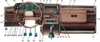
Electrical diagram of the VAZ-2110 car
| Relay/fuse no. | Decoding |
| 1 | Block headlight |
| 2 | Front brake pad wear sensors |
| 3 | Fan motor switch |
| 4 | Engine cooling fan motor |
| 5 | Sound signal |
| 6 | Generator |
| 7 | Oil level sensor |
| 8 | Carburetor solenoid valve control unit |
| 9 | Heater controller |
| 10 | Recirculation valve switch |
| 11 | Heater control lever illumination lamp |
| 12 | Switch |
| 13 | Carburetor limit switch |
| 14 | Oil pressure warning light sensor |
| 15 | Spark plug |
| 16 | Carburetor solenoid valve |
| 17 | Coolant temperature gauge sensor |
| 18 | Ignition distributor sensor |
| 19 | Ignition coil |
| 20 | Starter |
| 21 | Heater fan motor |
| 22 | Additional resistor for heater motor |
| 23 | Speed sensor |
| 24 | Reversing light switch |
| 25 | Micromotor gearbox for heater damper drive |
| 26 | Recirculation valve |
| 27 | Brake fluid level sensor |
| 28 | Blocks for connecting the rear window washer motor |
| 29 | Accumulator battery |
| 30 | Windshield washer motor |
| 31 | Washer fluid level sensor |
| 32 | Coolant level sensor |
| 33 | Windshield wiper motor |
| 34 | Mounting block |
| 35 | Blocks for connecting the warning light harness |
| 36 | Outdoor Light Switch |
| 37 | Instrument cluster |
| 38 | Rear fog light switch |
| 39 | Fog light warning lamp |
| 40 | Rear window heating indicator lamp |
| 41 | Watch |
| 42 | Heated rear window switch |
| 43 | Understeering's shifter |
| 44 | Block for switching wires when installing headlights of a different type |
| 45 | Instrument lighting control |
| 46 | Ignition switch |
| 47 | Connectors for connecting the headlight cleaner wiring harness |
| 48 | Portable lamp socket |
| 49 | Front interior lamp |
| 50 | Brake light switch |
| 51 | Interior lighting |
| 52 | On-board control system unit |
| 53 | Fuel gauge sensor |
| 54 | Hazard switch |
| 55 | Driver seat belt sensor |
| 56 | Cigarette lighter |
| 57 | Ashtray light |
| 58 | Glove compartment lamp switch |
| 59 | Connector for on-board computer |
| 60 | Glove compartment lamp |
| 61 | Side turn signals |
| 62 | Switches in the front door pillars |
| 63 | Switches in rear door pillars |
| 64 | Parking brake warning light switch |
| 65 | Trunk light |
| 66 | Temperature sensor for heating system |
| 67 | Exterior tail lights |
| 68 | Interior tail lights |
| 69 | License plate lights |
| 70 | Rear window heating element |
| 71 | Block for connecting an additional brake light |
* In the instrument panel wiring harness, the second ends of the white, black, orange, white with red stripe and yellow with blue stripe wires are connected to each other at the same points.
The electrical circuits of the VAZ-2111 and VAZ-2112 cars differ (with the exception of the engine control system) only in the addition of a tailgate cleaner and washer.
Electrical diagram of a VAZ-21102 car with a distributed fuel injection system ("January-4" controller)
| Relay/fuse no. | Decoding |
| 1 | Block headlight |
| 2 | Front brake pad wear sensors |
| 3 | Sound signal |
| 4 | Cooling fan |
| 5 | Reversing light switch |
| 6 | Accumulator battery |
| 7 | Generator |
| 8 | Oil pressure warning light sensor |
| 9 | Oil level sensor |
| 10 | Spark plug |
| 11 | Injectors |
| 12 | Idle speed control |
| 13 | Electronic control unit sockets |
| 14 | Throttle position sensor |
| 15 | Crankshaft position sensor |
| 16 | Ignition module |
| 17 | Coolant temperature gauge sensor (for instrument cluster) |
| 18 | Starter |
| 19 | Diagnostic block |
| 20 | Coolant temperature sensor (for engine management system) |
| 21 | Speed sensor |
| 22 | Fuel pump relay |
| 23, 35, 39 | Fuses |
| 24 | Electric fuel pump |
| 25 | Micromotor gearbox for heater damper drive |
| 26 | Recirculation valve |
| 27 | Heater fan |
| 28 | Windshield washer pump |
| 29 | Washer fluid level sensor |
| 30 | Brake fluid level sensor |
| 31 | Coolant level sensor |
| 32 | Wiper motor |
| 33 | Additional heater fan resistor |
| 34 | Injection power supply relay |
| 36 | Canister purge valve |
| 37 | Mass air flow sensor |
| 38 | Cooling fan relay |
| 40 | Outdoor Light Switch |
| 41 | Knock sensor |
| 42 | Oxygen concentration sensor (heated lambda probe) |
| 42* | CO potentiometer (installed on cars running on leaded gasoline; in this case, an oxygen concentration sensor is not installed) |
| 43 | Fog light warning lamp |
| 44 | Rear window heating indicator lamp |
| 45 | Fog light switch |
| 46 | Heated rear window switch |
| 47 | Instrument cluster |
| 48 | Mounting block |
| 49 | Fuel level sensor |
| 50 | Ignition switch |
| 51 | Instrument backlight brightness control |
| 52 | Understeering's shifter |
| 53 | Heater control lever illumination lamp |
| 54 | Hazard switch |
| 55 | Electronic heater control unit |
| 56 | Recirculation valve switch |
| 57 | On-board control system display unit |
| 58 | Side turn signals |
| 59 | Temperature sensor for heating system |
| 60 | Interior lighting |
| 61 | Front interior lamp |
| 62 | Portable lamp socket |
| 63 | Digital Watch |
| 64 | Switches in the front door pillars |
| 65 | Switches in rear door pillars |
| 66 | Glove compartment lamp |
| 67 | Glove box light switch |
| 68 | Cigarette lighter |
| 69 | Ashtray lamp |
| 70 | Brake light switch |
| 71 | Rear window heating element |
| 72 | Exterior tail lights |
| 73 | Interior tail lights |
| 74 | License plate lamps |
| 75 | Trunk light |
Electrical diagram of a car with a sedan body (except for components and parts of the injection system):
Electrical diagram of a car with a station wagon body (except for components and parts of the injection system):
SEE ALSO - fuses and relays for...:
LADA GRANTA
LADA KALINA
LADA KALINA 2
LADA LARGUS
LADA PRIORA
LADA VESTA
VAZ 2104, 2105
VAZ 2106
VAZ 2107, 21047
VAZ 2108, 2109, 21099
VAZ 2113, 2114, 2115
VAZ 2121, 21213, 21214
VAZ 2112 fuse box
If some devices on your VAZ 2112 car have stopped working, fuses or relays may be to blame. At the very least, the first thing you need to do is check them, and then draw some conclusions regarding the malfunctions. Correct diagnosis of many electrical problems will allow you to accurately determine the cause of the inoperability of a particular unit. To find out what fuses and relays do and how to find the right one, read this article.
Scheme
K1 – relay for monitoring the health of light bulbs; K2 – front wiper relay; K3 – repeater and alarm relay; K4 – low beam relay; K5 – high beam relay; K6 – additional relay; K7 – relay for turning on the heated rear window; K8 – backup relay (not installed on 110 series vehicles);
F1-F20 in the diagram are fuses. The circuits in the car are protected by fuses based on a certain rated current (in A). The battery charging circuit, generator circuit, ignition and engine starting are exceptions.
To replace a faulty fuse, first find the one that has blown, then eliminate the reason why it was damaged and then install a new one. Below is a list of fuses and information on each one.
Where is the cooling fan relay on the VAZ-2110
In order for everything to work correctly in the VAZ-2110 engine, it is necessary to maintain a certain temperature.
This temperature range is achieved using a cooling fan, which, as a rule, comes with an electric drive. Its activation and deactivation is carried out automatically. Moreover, if the machine contains a carburetor engine, then TM 108 is used, and in the case when an injection engine is used, a controller is used. This article will tell you where the cooling fan relay is located on a VAZ-2110 car. If the fan is controlled by switching on, it is important that the temperature setting of the housing sensor is observed. The sensor is considered faulty when its temperature has reached the switch-on level, and the cooling motor has not worked. To check, you should close the contacts of the sensor, then check whether the fan works; if so, then the sensor needs to be replaced with a new one.
There are times when closing the contacts does not help and the fan still does not work, then according to the diagram, the integrity of the fuse with the supply wires is checked.
In order to start the cooling fan of the machine in which the injection engine is located, an electronic controller is used. Temperature conditions are pre-entered into the device software and range from 100 to 105 degrees. If the temperature sensor is faulty, then a system error is selected on the controller, and the cooling fan is activated when the car engine is turned on.
A number of breakdowns occur in which the controller does not detect the breakdown, and as a result, when the required temperature reaches 105 degrees, the fan simply does not start. To perform the test, remove the temperature sensor connector while the engine is running. If the system is working properly, the sensor will start the cooling fan, and by returning the connector to its original position, the fan will turn off. In case of damage to the circuit, check the quality of the relay, fuse and underwater wires. Everything must be installed exclusively according to the diagram. To carry out express checks, they bridge terminals 30 and 87 of the fan relay, which are located in the heating shaft. To make it easier to find, look in the passenger seat area.
When the fan is activated, connect the control lamp, the housing and output 86 of the relay, then the relay will operate and the fan will start automatically. At the same time, it is necessary to manipulate such a circuit only when the relay is located in the connector block. Here it is recommended to look at the controller and the wire, the relay connector with pin 46, if there is a breakdown in one of them. If a specific click of the relay did not occur, but a positive signal goes from the main relay to pin 85, or there was a click, but the cooling fan did not start, then this indicates a breakdown of the relay and the need to replace it.
Checking burnt elements
Motorists should understand how to check the fuses in their car. An overload in the electrical network does not always lead to failure of the fuses themselves. They are the easiest to check, so diagnostics usually start from here.
When an electrical appliance stops functioning, it is far from certain that the protective element is to blame. Here the most correct and rational solution would be to check the status of the device responsible for the faulty device in the car.
A fuse map will be a very useful tool in the diagnostic process. On all modern cars it is located directly on the cover of the safety block.
There are several main verification methods:
- visual,
- replacement method
- multimeter.
The simplest method is considered to be by replacement. You just need to install a new fuse in place of the potentially faulty device. But it is fair to consider this technique identical to visual inspection. After all, it is easier to determine by external aspects than to change each of the fuses located in the block in a row.
Visual inspection
Let's start with how to understand whether a fuse has blown in a car, based purely on the appearance of the element. This method is considered the most correct, since it is quite easy for many people to visually verify that a breakage of a low-melting component has occurred.
To check, you will need to remove the element, bring it to the light and look at it carefully. It will not be difficult for an experienced motorist to find out and understand whether the fuse in his car has blown or not. Beginners do not understand this right away, which raises several more questions regarding how to get an accurate answer.
A worn fuse is not difficult to identify. This manifests itself in the form of broken wire (low-melting alloy) or burnt marks. Symptoms such as these indicate that the electrical circuit has broken and the fuse needs to be replaced.
A similar testing method is relevant for those fuses that are made from glass or transparent plastic. Most of them are found in passenger cars.
But the method also has a significant drawback. The test is performed by a person, without the use of any instruments. In some cases, especially for beginners, a visual examination does not provide a 100% guarantee of a correct diagnosis. Therefore, it is much more correct and efficient to check fuses using multimeters.
Checking with a multimeter
This is a great way to identify a blown fuse in your car. Anyone can calculate using this method, since there is nothing particularly complicated in the procedure. The only condition is to have a multimeter. You can also check with a regular tester, but a multimeter can later solve a number of other issues. This is a more versatile device. Having a car multimeter in your hands, you should understand in more detail how to independently check a potentially blown fuse.
Using such a device, verification is performed using 2 methods:
- by voltage,
- by resistance.
Let's start with a technique that involves checking the condition by voltage. Here you need to perform the following procedures:
- turn on the measuring device in voltage test mode,
- turn on the electrical circuit of the machine where there are problems,
- check the voltage parameters on one terminal of the protective element, and then on the second,
- if there is no voltage at one of the terminals, the device has burned out and needs to be replaced.
The method is extremely simple, for which it is appreciated by motorists. Just a couple of minutes is enough to verify that the fuse is working or confirm that it has failed.
But in certain situations, checking by voltage is not very easy. This mainly concerns the fuses responsible for the operation of the horn and door lock. This is where an alternative method comes to the rescue.
If for some reason the voltage test is not suitable for you, use the resistance diagnostic method.
- The multimeter switches to Ohm measurement mode. These are units of resistance
- the terminals of the measuring device are connected to the terminals of the fuse,
- if the screen is zero, the element has failed and needs to be replaced.
And there is nothing complicated here, because even a novice motorist who has only recently started operating a vehicle independently can easily cope with the task.
In fact, to check you only need a little free time and a good multimeter with the appropriate measurement modes. It’s not difficult to buy a device, but its capabilities are enormous in terms of self-diagnosis of a car.
Replacing classic fuses
This type of fuses was widely used in classic AvtoVAZ models and the first Samaras. It is a rod made of plastic or ceramics, with a fusible insert of a certain width made of thin metal placed on it. It is this insert that breaks when a short circuit occurs in the car wiring. Such fuses are installed between two metal legs of the block - each between its own pair.
Classic “finger” fuses are installed between two elastic legs.
To replace the “finger” fuse, you just need to pull it out from the space between the tabs, slightly pressing the movable tab (the second, as a rule, is rigidly fixed in the block). The new fuse is inserted in the same way. In this case, you need to make sure that the ends of the fuse are installed in the holes or recesses on the legs and that it does not dangle in its place.
A well-known disadvantage of classic mounting blocks with “finger” fuses is that the legs lose their elasticity over time and can move away from each other. Therefore, if the new fuse continues to dangle even after correct installation, remove it, press the movable tab towards the top (reducing the gap between them) and insert the fuse back.