Engine repair is considered the most difficult thing in a car, because no other part contains such a huge number of interconnected elements. On the one hand, this is very convenient, because if one of them breaks down, there is no need to change the entire assembly; it is enough to simply replace the failed part; on the other hand, the more component elements, the more complex the device and the more difficult it is for those who I'm not very experienced in car repairs. However, with a strong desire, anything is possible, especially if your zeal is supported by theoretical knowledge, for example, in determining the tightening torque of the main and connecting rod bearings. If for now this phrase is a set of incomprehensible words for you, be sure to read this article before getting into the engine.
Sliding bearings, their types and role in the operation of internal combustion engines.
Main and connecting rod bearings are two types of plain bearings. They are produced using the same technology and differ from each other only in the inner diameter (for connecting rod liners this diameter is smaller).
The main task of the liners is to convert translational movements (up and down) into rotational ones and ensure uninterrupted operation of the crankshaft so that it does not wear out prematurely. It is for these purposes that the liners are installed under a strictly defined gap, in which a strictly specified oil pressure is maintained.
If this gap increases, the engine oil pressure in it becomes less, which means that the journals of the gas distribution mechanism, crankshaft, and other important components wear out much faster. Needless to say, too much pressure (reduced clearance) also does not bring anything positive, since it creates additional obstacles in the operation of the crankshaft; it may begin to jam. That is why it is so important to control this gap, which is impossible without using a torque wrench in repair work, knowledge of the necessary parameters that are prescribed by the manufacturer in the technical literature on engine repair, as well as observing the tightening torque of the main and connecting rod bearings. By the way, the tightening force (torque) of the connecting rod and main bearing cap bolts is different.
Please note that the given standards are relevant only when using new sets of parts, since the assembly/disassembly of a previously used unit due to its wear and tear cannot guarantee compliance with the required clearances. Alternatively, in this situation, when tightening the bolts, you can focus on the upper limit of the recommended torque, or you can use special repair bushings with four different sizes, differing from each other by 0.25 mm, provided that the crankshaft is ground until the minimum gap between rubbing elements will not be 0.025/0.05/0.075/0.1/0.125 (depending on the existing gap and the repair product used).
The process and procedure for tightening cylinder head bolts on a VAZ 2109
Repairing a cylinder head cannot be called a simple procedure, which requires certain skills and some experience. Repairs require special tools. As a rule, during this work the gasket is changed and the cylinder head tightening torque is adjusted: VAZ 2109 in our case. In order for the adjustment to be performed correctly, you must strictly follow the instructions. With a competent approach, you will successfully carry out the adjustment, achieving the desired result.
The majority of today's cars do not need tightening of the head bolts, but on the VAZ 2109, it is required at least to undergo maintenance.
If moisture begins to accumulate in those places where the block comes into contact with the cylinders, then this is a sure sign that urgent tightening of the bolts is required. Moisture in the above areas is a sign of a lubricant leak. The main reasons for tightening bolts are:
- damage to the cylinder head due to engine overheating;
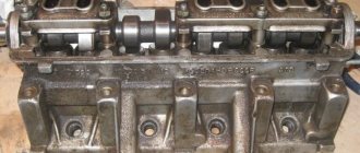
Cylinder head
- loss of tightness of the cylinder head gasket;
- the mileage specified in the instructions has been completed.
Video.
The internal combustion engine structurally has a large number of associated parts, which experience significant loads during operation of the internal combustion engine. For this reason, assembling a motor is a responsible and complex operation, for the successful implementation of which the technological process must be followed. The performance of the entire power unit directly depends on the reliability of fixation and the accuracy of fit of individual elements. For this reason, an important point is the accurate implementation of the calculated interfaces between mating surfaces or friction pairs. In the first case, we are talking about attaching the cylinder head to the cylinder block, since the cylinder head bolts must be pulled with a strictly defined force and in a clearly designated sequence.
As for loaded rubbing pairs, increased demands are placed on the fixation of connecting rod and main plain bearings (main and connecting rod bearings). After engine repair, during the subsequent assembly of the power unit, it is very important to maintain the correct tightening torque of the main and connecting rod bearings of the engine. In this article we will look at why it is necessary to tighten the bearings with a strictly defined force, and also answer the question of what is the tightening torque for the main and connecting rod bearings.
Read in this article
Puff
Reassembling the unit if you strictly follow the instructions for dismantling work will not pose any particular problems.
An incredibly important aspect of replacing the cylinder head gasket and all other activities associated with removing the head is the correct adjustment and tightening of the bolts.
Tightening the bolts is done strictly with a torque wrench, which will allow you to control the tension torque.
Here are some guidelines for using this specialized wrench and checking the current tension condition:
- Place the holder in the zero position. This will indicate that now the key data is equal to the moment of the original position;
- Look at the torque tool readings as you begin to tighten the bolts;
- Rotate the holder, monitor the indicators;
- If the torque does not change, the fastener may be stretchable, which is normal. This is exactly what should happen;
- If the torque increases rapidly, bolt movement should be achieved. That is, the stretch of the holder is small, it needs to be stabilized.
Golden rules of tightening
To properly reassemble the cylinder head, you need to adhere to the golden rules:
- Strictly follow the tightening torque data corresponding to the VAZ 2109;
- Make adjustments only using a torque wrench. Other tools do not allow you to get the desired result;
- To install the cylinder head, use only serviceable bolts that meet the requirements of your engine installed on the VAZ 2109;
- Before work, make sure that the holders are in good condition.
What are plain bearings
To better understand why engine bearings need to be tightened to a certain torque, let's take a look at the functions and purpose of these elements. Let's start with the fact that these sliding bearings interact with one of the most important parts of any internal combustion engine - the crankshaft. In short, the reciprocating motion of the piston in the cylinder is converted into rotational motion precisely thanks to the connecting rods and crankshaft. As a result, torque appears, which is ultimately transmitted to the wheels of the car.
The crankshaft rotates constantly, has a complex shape, experiences significant loads and is an expensive part. To maximize the service life of the element, connecting rod and main bearings are used in the crankshaft design. Taking into account the fact that the crankshaft rotates, as well as a number of other features, conditions are created for this part that minimize wear.
For the manufacture of liners, softer materials are used compared to those from which the crankshaft itself is made. The liners are also additionally coated with an anti-friction layer. Lubricant (motor oil) is supplied under pressure to the place where the liner is connected to the crankshaft journal. The specified pressure is provided by the oil pump of the engine lubrication system. In this case, it is especially important that there is the required clearance between the crankshaft journal and the plain bearing. The quality of lubrication of the rubbing pair, as well as the engine oil pressure in the engine lubrication system, will depend on the size of the gap. If the gap is increased, then the lubricant pressure decreases. As a result, rapid wear of the crankshaft journals occurs, and other loaded components in the internal combustion engine also suffer. In parallel with this, a knock appears in the engine.
Installing the connecting rod and piston group
The connecting rod and piston group (CPG) must be installed as an assembly. It is not recommended to press the piston pin into the connecting rod head without special tools. This procedure is best left to professionals.
To install the ShPG, you need a steel mandrel in the shape of a ring. The height of the ring is 2-3 cm, the diameter of the hole is slightly larger than the diameter of the cylinder. The pistons must be mounted in such a way that the arrow on their bottom (the part adjacent to the valves) is turned towards the oil pump. The number of the connecting rod and piston must correspond to the number of the cylinder. Before installation, you need to separate the locks of the oil scraper and compression rings at an angle of 120 degrees.
Installation algorithm.
- Turn the block over.
- We wipe the cylinder walls and crankpins with a dry cloth.
- Thoroughly lubricate the cylinder walls, the side surfaces of the pistons and the inside of the mandrel with oil.
- We place the mandrel on the cylinder and insert the piston and connecting rod assembly through it. We push the piston into the cylinder using a round wooden stick (hammer handle).
- Place the liner in the connecting rod cover and lubricate it with oil.
- We lay the block on its side and install the connecting rod cap so that the cylinder number on it and on the connecting rod are on the same side. We secure the cover with nuts.
- In the same way we mount the remaining pistons and connecting rods. After this, turn the cylinder block upside down and tighten all 8 nuts securing the connecting rod caps.
If you don't have a mandrel, you can cut it yourself from a piece of thick-walled steel pipe.
The VAZ 2108 engine assembly process is as follows:
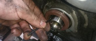
- First of all, it is necessary to install the liners in the cylinder block bed. But first you need to clean them from carbon deposits and oil deposits using a suitable metal rod. Do not use sandpaper. We clean only with a rod and periodically rinse everything with clean gasoline. After the beds are clean, install the liners according to the marks made during. The liners have locking lugs that should fit into the grooves on the beds. The middle liner will have no groove. After installation, lubricate them with clean engine oil.
- We install the crankshaft into the engine block on the bed.
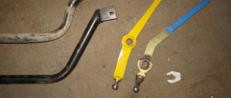
- Now we install the thrust half rings. Before installing them, rinse them from dust in clean gasoline. If you look at the half ring, you will see grooves on one side. These grooves are used to install the half rings to the crankshaft cheeks.
- A white steel-aluminum half-ring is installed on the camshaft drive side, that is, on the front side of the middle bed of the crankshaft, and a dark half-ring is installed on the opposite side of the bed.
- After installing all the half-rings, adjust their position so that their ends are flush with the ends of the bed and you can begin installing the liners.
- Rinse the bearings with clean gasoline, then install them in the main bearing caps in accordance with the marks made during disassembly. When installing, the antennae on the liner must coincide with the grooves of the covers. Also, before installing them, lubricate the bearings with clean engine oil.
- Now that all the liners are in place according to the previously made marks. Lubricate the holes for the fastening bolts on the covers, plus the bolts themselves and their heads with engine oil. We tighten all the bolts securing the covers, but do not tighten them. The bolts must be tightened in the following sequence: 3 2 4 1 and then 5 covers. After tightening, turn the crankshaft several times, it should rotate freely without jamming.
- After tightening the bolts, install the oil pump. Replace the oil pump gasket, which must be lubricated with any grease before installation so that it adheres well to the cylinder block.
- Install the crankshaft rear oil seal holder in the same way. We also change the sealing gasket, which we fix with grease.
- At the next stage of repair work, we assemble the pistons. According to the marks made during disassembly (if the piston group is installed with an old one), we lay out the pistons with connecting rods and their pins, prepare two new retaining rings for the piston pins.
- Install one retaining ring into place in the piston.
- Next, you need to heat the connecting rod head to 240° in the oven, after which we clamp it in a vice and put the piston on it. Place the piston pin in, pressing it in using a mandrel of suitable diameter. Do the work quickly so that the connecting rod head does not have time to cool down, otherwise the piston pin will not fit.
- After the connecting rod has cooled, lubricate the piston and pin with clean engine oil, which is poured through the hole in the piston boss.
- Install the remaining retaining ring.
- Next, install the piston rings. First of all, we put on the oil scraper ring expansion spring.
- Next, install the compression rings. A special device is used to install them. If it is missing, carefully separate the ends of the rings by hand and put them on the piston.
- In general, it is necessary to install the oil scraper ring first, then the lower compression ring and the middle compression ring last. If you look at the compression rings, you will see marks on their surface - “TOP”, “VAZ” or “Top” and the ring is installed so that this mark faces up. If these inscriptions are missing, the ring can be installed in any way.
- The lower compression ring is also slightly different. First of all, the difference lies in the thickness of the ring, plus there are grooves on one side. In this case, the ring is installed with the groove down.
- After installing the rings, check the quality of their rotation in their grooves. The rings should rotate easily without jamming. Before installing the piston into the cylinder, install the rings so that their locks are located at an angle of 120° to each other.
- Now we proceed to install the piston into the cylinder. The pistons are installed according to the marks made during disassembly. Before installation, carefully wipe the surface of the cylinder mirrors and the surface of the piston with a clean rag. Wipe surfaces with clean motor oil. Insert the liner into the connecting rod according to the marks made, so that the antennae of the liner fit into the grooves in the connecting rod.
- We put a special mandrel on the piston to compress the piston rings.
- Next, we need to rotate the crankshaft so that the installed piston is at bottom dead center.
- When installing the pistons, the arrow on the bottom of the pistons on the inside should be directed towards the front of the engine.
- Press the mandrel firmly against the cylinder block and use the wooden handle of a hammer to push the piston into the cylinder.
- Next, we need to insert the liner into the connecting rod cover and install the cover itself. We insert the insert in accordance with the marks made during disassembly. Lubricate everything with clean engine oil.
- Tighten the two nuts securing the connecting rod cover.
- Install the remaining pistons.
And at the final stage of assembly, we fasten all the hanging elements, namely:
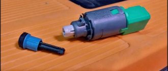
- Oil pressure sensor.
- We install the oil receiver.
- We install the oil sump, having first replaced the sealing gasket with a new one and secured it with any grease.
- Install the cylinder head, camshaft drive gear and drive belt with cover.
At this point, the repair work on the work is completed.
1. Remove the engine from the VAZ 2108, VAZ 2109, VAZ 21099 (see “Removing the engine”). 2. Place the engine on strong supports. 3. Carefully remove the gearbox. Make sure that the splined end of the input shaft does not rest on the diaphragm spring petals. 4. Remove the clutch from the engine (see “Clutch repair” in section 5 “Transmission”). 5. Remove the camshaft drive belt, the tension roller and the spacer washer installed under it (see “Replacing the camshaft drive belt on VAZ 2108, VAZ 2109, VAZ 21099 cars and adjusting the belt tension”) (see “Replacing the tension roller”) . 6. Remove the camshaft gear (see “Replacing the cylinder head gasket”).
7. Unscrew the four bolts (three of them also secure the water pump) and the nut securing the rear camshaft drive belt cover, and remove the cover.
8. Insert a screwdriver between the water pump housing flange and the block, and slide the water pump out of its seat. Remove the water pump. 9. Remove the head from the cylinder block (see “Replacing the cylinder head gasket”).
10. Unscrew the sixteen oil sump mounting bolts and remove the oil sump along with the gasket.
11. Unscrew the three bolts securing the oil receiver (spring washers are installed under the bolt heads) and remove the oil receiver.
12. Unscrew the bolt (a spring washer is installed under the bolt head) securing the oil level sensor in the oil sump. Remove the oil level sensor from the cylinder block. If necessary, rotate the crankshaft so that the crankshaft counterweight does not interfere with removing the oil level sensor.
13. Rotate the crankshaft so that the piston to be removed is at bottom dead center (BDC). Unscrew the two nuts securing the connecting rod cover.
14. Remove the connecting rod cover. If dismantling the connecting rod cover is difficult, first remove the connecting rod cover with gentle blows of a hammer. The cylinder number on the connecting rod cap may not be visible; in this case, mark the connecting rod cap with the cylinder number.
15. Push the connecting rod with the handle of a hammer into the cylinder and carefully remove the piston and connecting rod from the cylinder. At the same time, make sure that the lower head of the connecting rod does not touch the cylinder mirror, otherwise the mirror may be damaged. Remove the remaining pistons in the same way.
NOTE If you intend to remove the piston from the connecting rod, mark the piston with the cylinder number to avoid mixing up the pistons during installation. The cylinder number is stamped on the connecting rod, just like on the cover; if it is not visible, mark the connecting rod.
16. Remove the flywheel (see “Removing, installing and troubleshooting the flywheel”).
17. Remove six bolts (spring washers are installed under the bolt heads), remove the crankshaft rear oil seal holder and gasket.
18. Remove the timing pulley from the crankshaft. If the key does not fit tightly in the crankshaft groove, remove the crankshaft key so as not to lose it.
19. Unscrew the six bolts (there are spring washers under the bolt heads), remove the oil pump and gasket.
20. Remove two bolts securing the five main bearing caps.
21. Remove the main bearing caps.
22. Remove the crankshaft.
23. Remove the crankshaft thrust half-rings on the middle support.
24. Remove the shells from the main bearing caps and from the cylinder block beds. If the liners are not supposed to be replaced, as you remove...
25... mark the bearings on the non-working side relative to the main bearing caps and beds.
26. If it is necessary to remove the brackets of the generator 1 and the engine mounts 2, unscrew the three bolts securing them and the supply pipe of the water pump, unscrewing the two bolts securing it.
27. Remove the piston rings with a special puller. If there is no puller, remove the rings from the piston by carefully opening the ring locks.
Assemble the engine as follows.
Place a clean cylinder block on the stand and screw the missing studs into it. Install the generator mounting bracket and secure it with two bolts.
Lubricate the bearing shells and thrust half rings of the crankshaft, as well as the pistons and oil seals with engine oil. When assembling the engine after repair, install new crankshaft oil seals.
Rice. 2.21. Installing the crankshaft thrust half-rings into the middle main bearing housings
Install liners with a groove in the 1st, 2nd, 4th and 5th seats of the cylinder block, and liners without a groove in the 3rd seat of the cylinder block and in the main bearing caps. Place the crankshaft in the main bearings and insert the thrust half rings () into the seat of the middle main bearing.
WARNING
The half rings should have their grooves facing the thrust surfaces of the crankshaft (an anti-friction layer is applied to the surface of the half ring on the side of the grooves). A cermet half-ring (yellow) is placed on the rear side of the middle support of the crankshaft, and an aluminum-steel half-ring is placed on the front side.
Rice. 2.22. Marks on the main bearing caps. The caps are counted from the drive side of the camshaft
Install the main bearing caps in accordance with the marks on their outer surface (). Unfold the covers so that the marks on each of them are on the side where the generator is installed. Tighten the cover bolts.
Rice. 2.23. Checking the axial free play of the crankshaft
Check the axial free play of the crankshaft. To do this, turn the cylinder block with its back side up and install a stand with an indicator on it so that the indicator leg rests against the crankshaft flange. Moving the shaft up and down (for example, with screwdrivers), measure the axial free play of the shaft () with an indicator. It should be in the range of 0.06–0.26 mm. If the stroke is greater, then bring it back to normal by replacing the old half-rings with new ones or installing half-rings of increased thickness.
Rice. 2.24. Rear crankshaft oil seal holder. The arrows indicate projections for centering the holder relative to the crankshaft flange
Using mandrel 67.7853.9571, press the rear crankshaft oil seal into the holder (). Place the holder with the oil seal on the mandrel 67.7853.9572 and move it from the mandrel to the crankshaft flange. Place a gasket under the holder and attach it to the cylinder block with bolts and spring washers.
Rice. 2.20. Flywheel locking with clamp 67.7820.9526
Install the flywheel on the crankshaft so that the mark (cone-shaped hole) near the rim is opposite the axis of the crankpin of the fourth cylinder. Install the flywheel washer and bolts. Lock the flywheel with clamp 67.7820.9526 (see) and tighten the fastening bolts. Apply UG-6 sealant to the flywheel mounting bolts before installation. To ensure that the sealant adheres securely, degrease the bolts and threaded holes in the crankshaft before applying it.
Rice. 2.25. Installing the piston with piston rings into the cylinder using the mounting sleeve from kit A.60604
Select pistons for cylinders according to class and one weight group and assemble the pistons with connecting rods, as indicated in the “Connecting rod and piston group” subsection. Using the bushing from kit A.60604, insert the pistons with connecting rods () into the cylinders.
The kit includes bushings of normal and repair sizes of pistons. Therefore, it is necessary to select a sleeve suitable for the given size of the piston being installed. You can also use the adjustable bushing 67.7854.9517.
WARNING
The hole for the pin on the piston is offset from the axis by 1.2 mm, therefore, when installing the pistons into the cylinders, the arrow on the piston bottom should face towards the camshaft drive.
Install the bearings into the connecting rods and connecting rod caps. Install the connecting rods and caps onto the crankshaft journals and tighten the connecting rod bolts. The connecting rod caps must be installed so that the cylinder number on the cap is opposite the cylinder number on the lower end of the connecting rod.
Using mandrel 67.7853.9580, press the crankshaft front oil seal into the oil pump cover. Fill the oil pump with some engine oil and rotate the drive gear several times. Install the oil pump with the crankshaft front oil seal on the mandrel 67.7853.9580 and turn the drive gear to a position so that it can be placed on the crankshaft journal. Move the pump from the mandrel to the shaft, install a gasket under the pump and attach it to the cylinder block.
For proper installation of the pump, two guide pins () are pressed into its housing, which must fit into the corresponding holes in the cylinder block.
Rice. 2.19. Removing the oil pump: 1 – oil pump; 2 – oil pump gasket; 3 – oil pump receiver; 4 – crankcase gasket; 5 – crankcase
Insert the oil receiver with the O-ring into the hole in the oil pump, attach it to the oil pump and to the cover of the second main bearing of the crankshaft (see).
Install oil sump 5 with gasket 4 and secure it.
Lubricate the oil filter O-ring with engine oil and install the oil filter by hand screwing it to the fitting on the cylinder block.
Rice. 2.27. Bushings for centering the head on the cylinder block
Rice. 2.28. Cylinder head bolt tightening order
Insert two centering sleeves () into the cylinder block and install the cylinder head gasket over them. For a correctly installed gasket, the oil passage hole (edged with copper tape) should be in the area of the 5th cylinder head bolt (see bolt number).
WARNING
When reassembling the engine, you should always install a new cylinder head gasket. Used gaskets are not permitted.
Before installing the gasket, it is necessary to remove oil from the mating surfaces of the block and cylinder head. The gasket must be clean and dry. Oil should not come into contact with the surface of the gasket.
Rotate the crankshaft so that the pistons are in the middle of the cylinders.
Install the cylinder head, assembled in accordance with the instructions in subsection, onto the centering bushings. "Cylinder head". Tighten the cylinder head bolts in a specific sequence (). To ensure a reliable seal and avoid tightening the bolts during vehicle maintenance, tighten the cylinder head bolts in four steps:
1st step - tighten the bolts to a torque of 20 N·m (2 kgf·m);
2nd step - tighten the bolts to a torque of 69.4–85.7 N·m (7.1–8.7 kgf·m);
Step 3 - tighten the bolts 90°;
Rice. 2.65. Cylinder head bolt
WARNING
The cylinder head bolts may be reused only if they have been extended to a length L of no more than 135.5 mm (see). If the bolt is longer, replace it with a new one.
Before assembling the engine, lubricate the threads and bolt heads in advance by dipping them in engine oil. Then allow excess oil to drain by letting the bolts sit for at least 30 minutes.
Step 4 - tighten all the bolts again by 90°.
Insert the coolant pump with the gasket into the cylinder block socket. Install the rear timing belt cover and attach it together with the pump cover to the cylinder block. Additionally, attach the cover with a bolt to the cylinder block and a nut to the stud on the cylinder head.
WARNING
Before installing the coolant pump, make sure that the connection between the pump pulley and the roller is secure (see subsection “Cooling System”).
Insert segment keys into the slots at the front ends of the crankshaft and camshaft and install the toothed pulleys. Having blocked the camshaft pulley from turning, secure it with a bolt and washer.
WARNING
It is prohibited to replace the flywheel mounting bolts with the camshaft pulley mounting bolt and vice versa due to their different coating. The flywheel mounting bolts are phosphated, and the camshaft pulley mounting bolt is oxidized.
Rice. 2.29. Checking the alignment of the timing marks on the camshaft pulley and the rear protective cover
Using tool 67.7811.9509, turn the camshaft until the mark on the pulley aligns with the installation lug on the rear cover of the toothed belt ().
Rice. 2.30. Checking the alignment of the timing marks on the crankshaft pulley and the oil pump cover
Turn the crankshaft towards a smaller rotation angle until the alignment mark on the pulley aligns with the mark on the oil pump cover (). You can turn the crankshaft using a wrench using a bolt temporarily screwed into the front end of the crankshaft.
WARNING
It is prohibited to rotate the crankshaft with the cylinder head installed, as well as the camshaft if the pistons of any of the cylinders are at i.d.t. This will cause the pistons to strike the valves and damage the valve and crank mechanisms.
Install the tension roller with an axle (or without an axle if the roller has a plastic rim) and a spacer ring and secure it in the position of minimum belt tension.
Place the timing belt on the crankshaft pulley and, while tensioning both branches of the belt, put the left branch on the coolant pump pulley and place it behind the tension roller. Place the belt on the camshaft pulley and lightly tension it with the tension roller, turning the roller axis counterclockwise. When installing the belt, avoid sharp bends.
Rotate the crankshaft two turns in the direction of rotation and check that the alignment marks ( and ) are aligned. If the marks do not match, then loosen the belt tension, remove it from the camshaft pulley, turn the pulley to the required angle, put on the belt, slightly tension it with the tension roller, turn the crankshaft two turns again and check that the alignment marks match.
If the marks coincide, adjust the belt tension as described in subsection. "Camshaft and its drive."
Adjust the clearances in the valve mechanism as indicated in the “Cylinder Head” subsection. Install the front timing belt cover and secure it with bolts.
Carefully place the gasket into the groove of the cylinder head cover along the entire perimeter. Install the cover on the cylinder head, put the rubber bushings on the studs and attach the nuts and washers. If the bushings show signs of destruction, replace them with new ones. Tighten the nuts evenly in several steps until the washer rests on the stud. Remember that the tightness of the cover depends on the thoroughness of all installation operations.
Wrap the spark plugs and coolant temperature gauge and oil pressure warning light sensors into the cylinder head.
Rice. 2.31. Installation of cooling system components: 1 – supply pipe of the coolant pump; 2 – thermostat; 3 – outlet pipe of the cooling jacket
Install the outlet pipe 3 () of the cooling jacket with a gasket on the cylinder head and secure it with two nuts. Install the gasket and attach the flange of the inlet pipe 1 of the coolant pump to the cylinder block. Place the hoses leading to the thermostat onto the pipe and supply pipe, install thermostat 2 and secure the hoses with clamps.
Install the auxiliary housing with the O-ring on the cylinder head and secure it with a bolt. When installing the housing, pay special attention to the position of the sealing ring in the groove, since when tightening the nuts, it may jump out of the groove and bite between the edges of the groove and the surface of the cylinder head. If the sealing ring shows signs of being bitten, it must be replaced with a new one.
In accordance with the instructions in the “Fuel Pump” chapter, install the heat-insulating spacer with gaskets, the pusher and the fuel pump.
Rice. 2.32. Installation of the ignition distributor sensor. The arrow indicates the mounting protrusion on the housing of the auxiliary units
Lubricate with engine oil and place the O-ring on the flange of the ignition distributor. Attach the sensor-distributor to the body of the auxiliary units in such a position that the middle mark on the flange of the sensor-distributor is opposite the mounting lug on the body of the auxiliary units (). At the same time, install the high voltage wire bracket under the upper fastening nut. The ignition sensor-distributor shaft is connected to the camshaft shank in only one position. Therefore, before installation, rotate the shaft so that the cams of the shaft coupling fit into the grooves of the camshaft shank.
Rice. 2.33. Installation of the intake pipe and exhaust manifold: 1 – exhaust manifold; 2 – bracket for the supply pipe of the coolant pump; 3 – inlet pipe; 4 – warm air intake
Place gaskets on the cylinder head studs, install exhaust manifold 1 () and tighten the central nut securing it. Then install the inlet pipe 3, warm air intake 4, bracket 2 of the coolant pump inlet pipe and secure them with nuts.
Install the crankcase exhaust ventilation hose and secure it with clamps to the pipes of the block and cylinder head cover. Install the oil level indicator.
Rice. 2.13. Removing the generator: 1 – tension bar; 2 – generator; 3 – generator mounting bracket; 4 – generator drive belt; 5 – generator drive pulley
Place the generator drive pulley on the crankshaft and secure it with a bolt and washer. Install tension bar 1 (see) and generator. Place the belt on the crankshaft and generator pulleys and adjust its tension as indicated in the “Generator” subsection.
Install the carburetor heat shield, spacer and carburetor. Secure it with nuts and close the top with a technological plug.
WARNING
Do not fasten (or tighten the nuts) a heated carburetor. For the tightening torque of the carburetor mounting nuts, see Appendix 1.
Install the gasoline supply hose from the fuel pump to the carburetor and secure it with clamps. Install the hose of the vacuum regulator of the ignition sensor-distributor, as well as the hoses for supplying and discharging fluid from the cooling system to the carburetor.
Install hoses going to the heater on the outlet pipe of the cylinder head and on the inlet pipe of the coolant pump and secure them with clamps.
Rice. 2.12. Removing the fuel pump and ignition distributor: 1 – ignition distributor; 2 – bracket for fastening high-voltage wires; 3, 5 – sealing rings; 4 – housing of auxiliary units; 6 – heat-insulating spacer; 7 – pusher; 8 – fuel pump
Connect the high voltage wires to the ignition distributor and to the spark plugs. Secure the wire comb in bracket 2 (see).
Fill the engine with oil through the filler neck on the cylinder head cover.
views
Save to Facebook Save to Odnoklassniki Save to VKontakte
- How to submit application security to Sberbank AST In accordance with the law, public procurement tenders must be carried out...
- Pegasus Georgia. Georgia. Best prices for tours to Georgia →
How to tighten main bearings and connecting rod bearings
So, taking into account the above, it becomes clear that the tightening torque of the main and connecting rod bearings is extremely important. Now let's move on to the assembly process itself.
- First of all, molar liners are installed in the bed of the molar necks. Please note that the middle liner is different from the others. Before installing the bearings, the preservative lubricant is removed, after which a little motor oil is applied to the surface. After this, the bed covers are placed, after which the tightening is carried out. The tightening torque should be that recommended for the specific model of the power unit. For example, for engines on the VAZ 2108 model, this figure can be from 68 to 84 Nm.
- Next, the connecting rod bearings are installed. During assembly, it is necessary to accurately install the covers in place. The specified covers are marked, that is, their arbitrary installation is not allowed. The tightening torque of the connecting rod bearings is slightly less compared to the main bearings (the indicator ranges from 43 to 53 Nm). For Lada Priora, the main bearings are tightened with a torque of 68.31-84.38, and the connecting rod bearings have a tightening torque of 43.3-53.5.
Puff
Reassembling the unit if you strictly follow the instructions for dismantling work will not pose any particular problems.
An incredibly important aspect of replacing the cylinder head gasket and all other activities associated with removing the head is the correct adjustment and tightening of the bolts.
Tightening the bolts is done strictly with a torque wrench, which will allow you to control the tension torque.
Here are some guidelines for using this specialized wrench and checking the current tension condition:
- Place the holder in the zero position. This will indicate that now the key data is equal to the moment of the original position;
- Look at the torque tool readings as you begin to tighten the bolts;
- Rotate the holder, monitor the indicators;
- If the torque does not change, the fastener may be stretchable, which is normal. This is exactly what should happen;
- If the torque increases rapidly, bolt movement should be achieved. That is, the stretch of the holder is small, it needs to be stabilized.
Golden rules of tightening
To properly reassemble the cylinder head, you need to adhere to the golden rules:
- Strictly follow the tightening torque data corresponding to the VAZ 2109;
- Make adjustments only using a torque wrench. Other tools do not allow you to get the desired result;
- To install the cylinder head, use only serviceable bolts that meet the requirements of your engine installed on the VAZ 2109;
- Before work, make sure that the holders are in good condition.
Checking the bolts