A story about how I repaired the Norma electrical package control unit. It all started with the fact that the driver's door electric lock stopped closing, I've already encountered this more than once, the teeth in the drive itself were cut off. I drove like this for two weeks, closing the driver's door with the key. But at one point, all the locks stopped closing, either from the alarm or from manually pressing the button in the driver's door. I replaced the drive with a new one, but that didn't help. 1. I tried to retrain the key fob again, it has not responded to pressing the buttons on the key fob for a long time. The training was successful, the key fob began to respond to button presses, and the car was set to normal security. But the door locks did not respond to closing. 2. I got to block 1118-6512010 “Norma”, I saw an unpleasant thing, the alarm installers assembled everything by twisting, without soldering. The wires for opening and closing the doors, from the alarm system, are connected to the second and seventh contacts of the block; they were soldered directly to the board, but quite efficiently; two holes for the wires were broken out in the case. Contacts from the ISO connector are suitable for this connector for connecting music in the car.
3. I cut off wires No. 2 and No. 7 from the “Nor”, nothing has changed, the drives are silent, inside the “Norma” you can hear the relays clicking. 4. No voltage is supplied to pin 14, 17, 18. 5. I disassembled the “Norma”, removed all the relays from the board, checked them, they all turned out to be working. 6. When you press the door lock button, ground appears along the blue wire (Contact No. 4). 7. I applied power directly from the battery to contacts 14 and 17 - all the doors except the driver's door closed, I also applied to 14 and 18, the driver's door closed, i.e. Drive wiring is correct. All the manipulations performed showed that some SMD components on the board had failed, I examined the board under a magnifying glass and did not find anything burnt out. 8. I went shopping for the “Norma” block, found it only at the car market, the stores in our small town of Sepversk didn’t have it, one store offered to deliver it to order in two weeks. It cost me quite a budget - 2000 rubles. In the store I came across two types of “Norma” 1118-6512010 and 1118-6512010-01, I took the one I had without the “-01” at the end, does anyone know what the difference is between them? 9. I left the store, immediately picked up the block, closed the door with the key, all the locks worked as expected, first they all opened, then they all closed. That is, the block is working and my wiring, as I said, is also all working. 10. I tried to close it using my own key fob, but there was no reaction. I retrained the key, now this manipulation took place at the level of automation, although at first I forgot to unhook the end on the diagnostic connector leading to BC STATE Matrix (this is very important as they write on the Internet). After training, the key fob worked as normal, opening and closing the doors.
11. I pulled out two contacts from the ISO connector (for connecting musical equipment), inserted them into contacts 2 and 7, and soldered the “green-white” and “blue-white” alarms to them. As I understand it, the impulse to “Norma” is supplied with negative polarity, so the “blue-red” and “green-red” wires are screwed to ground. I closed the doors with the signal, everything worked as expected.
While I was fiddling with “Norma” I re-read a bunch of all sorts of material, I realized that it is not so difficult to replace the key in the immobilizer bypass with a simple chip, otherwise you have to carry a red (training) key there. To retrain the key, I had to remove the dashboard and climb into the immobilizer bypass.
Double-glazed window control unit “Norma” 1118 – 6512010 for VAZ 11183 “Kalina”
©Aktuator On cars of the Kalina family, 2 types of non-interchangeable (by wiring) glass control controller 1118 - 6512010 and 11180 - 3763040 can be installed. 1118 – 6512010 has one 25-pin connection connector, 1118 – 3763040 (1118 – 3763040 – 10) – two connectors.
Remote control system for double-glazed windows “norm” on a VAZ 11183, Kalina. Controls power windows and central door locking. When the connector is removed, the engine does not start; the device performs some of the anti-theft functions.
Connection
* A regular shock sensor from any alarm system (Alligator, Saturn, Clifford, APS) is suitable.
+ 12 V connect to pin 12; body – on the 6th; We connect the signal wire (a ground appears on it at the moment of activity) to the 1st contact.
During normal arming, Kalina now reacts to an impact on the body (it sounds a horn and blinks turn signals). Similarly, instead of a shock sensor, you can connect a volume sensor (for example, single-level MMS‑1).
You can also connect a pager: + 12 V of the pager transmitter on pin 12, minus on pin 21.
Double-glazed window control unit 1118 – 3763040 (- 10 ) for VAZ 11183 “Kalina”
| Appearance | Controller board | Reverse side |
Double-glazed window control unit 2170 – 3763040 for VAZ 2170 “Priora”
1 . 1 Malfunction in the VZ communication coil circuit
1 . 2 Malfunction in the circuit from the block to the communication coil to the APS ECU
1 . 3 Transponder missing in OK
1 . 4 The transponder in OK is faulty (detected during pre-production preparation)
1 . 5 The transponder in the Republic of Kazakhstan is faulty (detected during pre-production preparation)
1 . 6 Malfunction of the input transponder circuit in the APS ECU
1 . 8 The communication coil came off from the VZ pad on the inside
2. 2 Malfunction of W‑Line circuits in the APS or ICS units
2. 3 Lack of supply voltage on the APS or KSUD unit
2. 4 The “Normal” electrical package is faulty (the control driver has burned out)
2. 5 KSUD does not contact
Abbreviations: IS – status indicator; VZ – ignition switch; OK – training key; RK – working key; RC – remote control; KSUD – engine control system controller; ECU - electronic control unit
Malfunction of the central locking system in the Chevrolet Niva is considered a fairly common problem, even after the 2010 restyling, when more reliable components began to be used. On new Chevrolet Niva cars, as a rule, central locking with a key or alarm key fob does not work. The doors have to be opened manually. You can fix the malfunction on your own, the main thing is to determine the cause of the breakdown and know the location of the relays and mechanisms.
If the central locking from the key fob does not work: troubleshooting sequence
p, blockquote 24,0,0,0,0 —>
Any repair or troubleshooting in a car must begin with checking the fuses that serve a specific system. There are three of them in the diagram below. Usually it can be more. You need to find their location using the car's instruction manual or searching on the Internet.
p, blockquote 25,1,0,0,0 —>
Video - if the central locking does not work from the alarm, then first check the fuses:
p, blockquote 26,0,0,0,0 —>
p, blockquote 27,0,0,0,0 —>
If all fuses are in good working order, proceed to determining the location of the malfunction based on its characteristic symptoms.
p, blockquote 28,0,0,0,0 —>
Central locking does not close the doors
There are several options for central locking:
p, blockquote 29,0,0,0,0 —>
- does not respond to the key fob signal at all, in this case it is necessary to check, or better yet, immediately change the key fob battery;
- does not close the door even with the lock key;
- closes and immediately opens the doors.
The last option is associated with loose closure of windows or doors. It is necessary to try to press each door sequentially, supporting it with your whole body, and at the moment of pressing, try to close the central locking.
p, blockquote 30,0,0,0,0 —>
Perhaps a foreign object has gotten into the closing area of a door; it needs to be checked. You should also check the pressure of the glass so that it fits tightly into the upper grooves.
p, blockquote 31,0,0,0,0 —>
If the central lock does not respond to the key fob and key, the wires may have broken in the area of the corrugation entering the door. If you have experience repairing electrical wiring, you can find the faulty wire and connect it.
p, blockquote 32,0,0,0,0 —>
The central locking system does not open the doors, but at the same time closes them
One option is to shift the door hanger. The lock is locked with a door latch. This type of malfunction often occurs in the trunk doors. You have to press them manually to wedge the movement of the lock drive. When you try to open the door, you should hear a click from the drive. In some cars it is almost inaudible; you have to put your ear to the door.
p, blockquote 33,0,0,0,0 —>
Central locking only closes the driver's door
Here, most likely, the malfunction is a breakdown in communication from the driver's door control unit to the central unit or other doors. You should remove the corrugated hose from the wiring transition from the driver's door to the car interior - there will be a break there.
Causes of central locking malfunctions
Most often, the electrical part of the solenoids control fails, and the locks themselves are considered relatively reliable.
The central locking of a Chevy Niva car works on the following principle: the signal for opening or closing the doors is transmitted by pressing a button on the key or turning the cylinder in the driver's door, while the signal passes through the central locking control unit and the on-board computer.
This scheme has its weaknesses, and the main reasons for failure are the following factors:
- short circuit in the circuit and fuse failure;
- chafing of wiring in flexible corrugation, loss of contact at joints due to vibrations and moisture ingress;
- central locking relay malfunction;
- error in the central locking control unit;
- lock motor failure.
Advice! If the car has an alarm system, the central locking may not open due to a malfunction of the alarm system. Perhaps the reason lies in the dead battery of the alarm control panel.
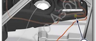
Car alarm connection points for Niva Chevrolet 2010
Driver's door – white/blue Passenger's door – yellow/black Rear doors – white/black trunk – white/red hood – green/black All limit switches are negative
Turns – blue and blue/black
Central locking block behind the mounting block. Central lock (-) – closing – 7th leg, opening – 2nd leg. To control the central locking, you need to solder to the block.
On this car, the first press of the standard key fob opens the driver's door, the second press opens the passenger door. One of the well-known sites has connection points using an additional relay. But I don’t think this method is the best. That's why I offer mine. The central locking unit on the Chevy Niva is from Kalina.
Operating principle and central locking diagram
Central locking has been installed on the VAZ 2123 since 2004. Since then, the Chevy Niva central locking scheme has not changed fundamentally and is installed on cars starting with the “Norma” configuration. To control the remote door opening, a remote control (remote control with a flip key) is used. It combines the functions of an immobilizer, ignition key, and door key. The signal from the remote control is received by the electrical package control unit (1118-6512010), which is responsible for opening the doors.
Pressing a button on the remote control opens or closes all car doors, including the trunk door. In the same way, the central locking is triggered when the key in the driver's door is turned half a turn to the right or left.
The operation of the electrical network is controlled by a standard relay type 90.3747, a 20 A fuse, limit switches in each door, and gear motors on the lock mechanisms.
A special feature of the Chevrolet Niva Central Locker is the ability to manually open and close the doors, even with the battery removed.
Important! The gearmotors are equipped with protection against overheating and turn off for a while after repeated activation of the central locking system.
How the system works
p, blockquote 11,0,0,0,0 —>
The central locking system includes the following main blocks and components:
p, blockquote 12,0,1,0,0 —>
- central electronic unit;
- driver's door electronic unit (can be combined with the central unit);
- electronic units for driver, passenger and rear doors (may be missing);
- push-button switches for driver, passenger and rear doors;
- limit switches for closing windows and doors;
- control units and window lift drives.
adsp-pro-1 —>
In most car models, the power window and central locking control units are connected into a single system. When closing the doors, the central locking system must poll the limit switches of all windows so as not to accidentally park the car and guard it with the windows open. Therefore, the failure to close the doors is often associated with a malfunction of the window regulator controls.
p, blockquote 13,0,0,0,0 —>
For a 2005 VW Passat, the electrical circuit for the central locking looks like this:
p, blockquote 14,0,0,0,0 —>
p, blockquote 15,0,0,0,0 —>
- Drive, buttons and limit switches of the passenger door (hereinafter referred to as Dv);
- Passenger engine control unit;
- Window lifter control unit and rear left drive;
- Rear left drive motor, switches;
- Driver's switch;
- Driver's driver's side switches;
- Driver's control unit, internal;
- Control unit for rear right door and window lifter;
- Multifunctional control unit.
- Blocker.
- Central locking drive rear right motor
- Window lifter switches and buttons.
- Fuses serving the central locking system.
This diagram does not show and label all the elements, but it is clear that the circuit is very complex, perhaps the most complex among the main electronic modules of a car.
p, blockquote 16,0,0,0,0 —>
At the same time, the central locking control circuit has the longest electrical wiring, which is distributed throughout the vehicle interior and has flexible corrugated hoses at the points of transition to the door space. Among other difficulties, car doors have maximum mobility relative to the interior; their interior space is susceptible to corrosion.
p, blockquote 17,0,0,0,0 —>
Despite the above difficulties, car models after the 2000 release have fairly reliable electronic central locking systems; their main malfunctions are often determined by mechanical breakdowns, faulty contacts, and wear on the door suspension.
p, blockquote 18,0,0,0,0 —>
Ways to solve problems with central locking Niva Chevrolet
Before starting work, it is recommended to evaluate your repair skills and experience with electrical wiring in a car. Special equipment may be required, and at a minimum, a tester is required to diagnose electrical circuits. Troubleshooting always starts from simple to complex.
Fuse failure
Most often, the cause of its burnout is a short circuit or overload in the circuit. In the mounting block of cars manufactured before 2009, it is designated F6; on cars after 2010, it is located under the number F10.
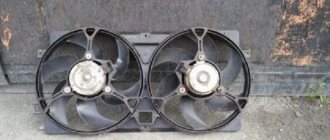
Gearmotors
Their breakdown does not occur often, but repairing or replacing motors in doors requires partial disassembly of the door and removal of the upholstery. A faulty motor can be detected by the silence on its part when the central locking system is activated or incorrect operation (does not open completely, fires every other time, extraneous sounds).
Functionality is checked with a multimeter or by connecting to the battery directly. Replace the gearmotors with a new assembly if the old one cannot be repaired.
Advice! It happens that the sounds of the motor operating are heard, but the door does not respond to signals from the key. In this case, it is necessary to check the rods coming from the locks to the gearmotors and door handles.
Wiring
In addition to the central locking system, alarm wires, limit switches, audio systems, and power windows enter the door. Despite the rational S-shaped bend of the door wiring in the corrugation, damage to one or more wires occurs. The second weak point is the contacts inside the door.
The integrity of the wiring is checked by “ringing” suspicious sections of the circuit. The found break is cleaned and connected by soldering or crimping bushings. Replacing a broken wire entirely with a new one is not always advisable due to the complexity of the work.
Relay circuit
Power to the central locking can be supplied through the main relay used for low beam headlights and interior lighting. There are also schemes with a separate relay for the central locking, which is installed next to the control unit of the door opening system.
Central locking control unit
This block is present only on cars with the “Norma” configuration and higher. A common reason for its failure is a short circuit in the circuit or large voltage surges, leading to melting of the microcircuit contacts. Diagnosed visually (traces of melting on the body) or with an electrical tester.
The central locking unit, as a rule, is not repaired and is simply replaced with a new one.
On-board computer (ECU)
On Chevy Niva, the central locking scheme on later cars involves the participation of the on-board computer in the processes of opening and closing doors, as well as setting the alarm. Such a scheme allows you to expand the functionality of the central locking system, connect an alarm system with auto start and make the operation of the car more comfortable.
Information about errors and malfunctions of the central locking is obtained through a scanner or PC, which is connected to the car via a standard OBD2 connector. Errors in the computer are one of the reasons why remote opening does not work. In the application you can reset errors and find out the cause of the problem. In difficult cases, the control unit is reflashed.
Central locking device for Niva Chevrolet
I already wrote earlier in the BZ that problems began with opening/closing doors from the remote control. The main problem was with the driver's door, but later the passenger's door became connected, as well as the right rear door. The essence of the problem is that the lock clicks, but does not close. You have to click again, or even close it with your finger, and then close the working door using the remote control. In general, it’s tough ((Not convenient.
I waited until it warmed up and decided to do it right away. An autopsy showed that all 5 retractors on the Chevrolet Niva are the same. Although I thought there would be a different one on the driver's door. But no. I decided to change all 5 at once, because... since 2 have already died and 1 is knocked out, it means the others will soon die.
The retractors cost me 1,500 rubles for 5 pieces. Plus I spent another 120 rubles on a bag of clips for attaching the trim, because... The doors had already been dismantled once to make noise; there was a fear that the relatives would not survive the second outrage. At least not all of them.
Removing the doors was no problem. I was pleased that all the sound insulation was in place. Nothing has come off, there is no dampness, there is no rot, everything is dry and clean. Pass! There is only dust. But where would we be without her?
The retractors are screwed to the lock frames, so they are not difficult to find. But to remove it... There is no problem here either. Don't try to find super flexible screwdrivers to get into somewhere. This is all a collective farm and it won’t work out properly anyway. Just unscrew the lock and then the retraction motor can be moved into the “window” of the door frame and you can easily change it. Then return the lock to its place.
Be careful when connecting the power terminals. You must immediately check that when you press the “close” button, the locks close, and when you press the “open” button, they open. If something is wrong, then switch the wires the other way around and everything will be fine.
When assembling, I strongly advise you to pull the wires together in a bunch, and also glue them to the door so that they do not dangle. Not a fact, but when shaking, loose terminals can cause unnecessary “crickets” in the cabin. Also look, knock on the door, listen, so that there are no other rattling parts. If there are, it is better to secure them immediately.
As a result, the locks work clearly and reliably. I'm happy))
Tips for motorists
Such a malfunction is “not fatal” for the car, but very unpleasant. Unfortunately, this problem occurs on this model. The problem can be either serious or not so serious, which you can easily fix yourself. That's what we'll talk about in this article. Malfunctions can be in the mechanical part, as well as in the electrical equipment of this system.
Where to look for a fault
Mechanical failures are the least likely to occur. This usually happens in winter, when moisture that gets into the locking mechanisms freezes, which creates an obstacle to opening or closing the car doors. This problem is solved after warming up the mechanisms. True, sometimes difficulties will arise with such an operation, especially when the door needs to be opened. To detect faults in electrical circuits, you will need a car tester or other similar measuring device, as well as skill in working with electrical equipment of cars.
We combine two different alarms
So, let's say that one alarm system in the Niva-Chevrolet is already installed (from the factory). This means that we will use the wires connected to its module initially. There are limit switch taps and ground, as well as central locking control wires.
The cable we are talking about is a power cable and is usually covered with yellow insulation.
Additional alarm connection diagram
To control all locks, and not just the driver’s actuator, you need to implement the following connection option:
Let's list the features of this option:
- The relay contacts built into the main unit are connected to the breaks in the signal wires (see figure);
- The normally open contact of the locking relay is left free. In “Shnivy”, closure occurs when the cord is “in the air”;
- The duration of the control pulse is set to “0.8 seconds”;
- The control output is programmed to be activated during unlocking. This output controls another, third relay.
Let's talk about why an additional relay is needed here. If we remove it, we will see that the passenger locks cannot be opened from the key fob. In principle, this option is also acceptable: except for remote unlocking of three doors, everything will work.
The 15 Amp fuse shown in the diagram is in series with the cable leading to the actuators.
Connecting without using a fuse is strictly prohibited. At the same time, it is not necessary to protect the relay windings with a pre-flask. The same applies to the signal wires, that is, to the normally open contact of the unlocking relay. In principle, fuses can be added to all three circuits. And also, the winding of the “lower” relay can be powered from the 87th contact.
Practical implementation of the scheme
Surely the reader knows where the fuse box is installed in the Niva-Chevrolet. This block must be dismantled by unscrewing one screw from the top.
A plastic box will be secured under the indicated block. She is exactly what we need.
There are three “important” cords on the connector of the module shown here: blue, blue-yellow, yellow. Taps from the three break points are extended to the installed signaling, as well as to an additional relay (see diagram). Particular attention should be paid to the connections of power wires.
You can make an additional relay module yourself. A current not exceeding 8 Amperes will flow through the contacts here, so there will be no difficulties:
The diode shown in the main diagram can be anything (its characteristics are not so important). The main thing is that it is there, otherwise you can burn out the control output to which the switched winding is connected.
Remember the main thing: you can carry out any installation work only when the negative terminal is disconnected from the battery.
It is better to connect power cables by twisting, but knowing how to do it correctly is an entire art. All connection points must be isolated. But this will not be enough: in places where the metal touches, the cord is protected with heat-resistant insulation. This is how you can protect yourself from unforeseen consequences.
Replacing the Chevrolet door lock fuse - Niva
All connection points must be isolated. But this will not be enough: Place an advertisement Feedback Team blog.
Unlocking locks in one click on Chevrolet Niva, Lada Priora, Lada Kalina...
The central locking does not work, it does not work either from the leopard alarm key fob or by hand. Maybe he still knows how to switch off? You should contact an alarm installer. If you pull the button on the driver's door, but the lock does not work, then perhaps the limit switch in the door is faulty - you need to check, for this you will have to disassemble the lock, and this is a pain in the ass:
If the button on the driver's door goes down and goes up when locking or unlocking the door. In this case, the limit switch works.
signal to the field
It also responds to signals and dimensions. I won’t tell you where to dig because I don’t know the complete diagram. We need to look - maybe when they installed the signaling they did a reconnection.
Features of programming the new signaling
Let's say the scheme discussed above was implemented without errors. At the second step, as you might guess, you need to correctly program the alarm. Otherwise, there is a possibility of burning out the actuators installed in the passenger doors. The advice is simple: you cannot make a control pulse longer than one second. However, the default value is 0.7 or 0.8.
The signal output used must also be programmed correctly (it must be activated at the moment of unlocking). An alternative method is to use the 2-step unlock output. The pulse duration on it must be set within 0.7-0.8 s. The default value is 30 s, and guess what this means in this case.
Some versions of the Niva-Chevrolet are equipped with central locking. If there really is a standard central locking system, it is controlled by a single module. It should be noted that this same module acts as a standard signaling device. It turns out that an alarm system with central locking is installed in the Shniva from the factory, but you can always connect an additional alarm to it, that is, to the standard module. One of the options for such a connection is discussed further.
General recommendations
p, blockquote 45,0,0,0,0 —>
Periodically open the door with the key, even if you always use the central locking key fob, so that the door lock mechanism does not get stuck.
p, blockquote 46,0,0,0,0 —>
Do not try to warm the lock with hot water if it is frozen in winter. It's better to try an electric hair dryer. Commercial liquids for freezing at low temperatures do not always help.
p, blockquote 47,0,0,0,0 —>
Tighten the door suspension, if it wobbles, this can lead to jamming of the lock and blown fuse for its power supply.
p, blockquote 48,0,0,0,0 —>
It happens that the immobilizer does not see the key, what to do in such situations.
How can you determine which alarm system is used in a car using a key fob?
If the car windows sweat from the inside https://voditeliauto.ru/sovety-voditelej/zapotevayut-stekla-v-mashine-iznutri-chto-delat.html what to do in this case and what folk remedies can be used.
Video - repairing the central locking on a Hyundai Getz:
p, blockquote 50,0,0,0,0 —> p, blockquote 51,0,0,0,1 —>
We combine two different alarms
So, let's say that one alarm system in the Niva-Chevrolet is already installed (from the factory). This means that we will use the wires connected to its module initially. There are limit switch taps and ground, as well as central locking control wires.
The lock is controlled by two wires - yellow-blue and blue. In addition, you will need to find another cord that powers the passenger door actuators.
The cable we are talking about is a power cable and is usually covered with yellow insulation.
Additional alarm connection diagram
To control all locks, and not just the driver’s actuator, you need to implement the following connection option:
Let's list the features of this option:
- The relay contacts built into the main unit are connected to the breaks in the signal wires (see figure);
- The normally open contact of the locking relay is left free. In “Shnivy”, closure occurs when the cord is “in the air”;
- The duration of the control pulse is set to “0.8 seconds”;
- The control output is programmed to be activated during unlocking. This output controls another, third relay.
Let's talk about why an additional relay is needed here. If we remove it, we will see that the passenger locks cannot be opened from the key fob. In principle, this option is also acceptable: except for remote unlocking of three doors, everything will work.
The 15 Amp fuse shown in the diagram is in series with the cable leading to the actuators.
Connecting without using a fuse is strictly prohibited. At the same time, it is not necessary to protect the relay windings with a pre-flask. The same applies to the signal wires, that is, to the normally open contact of the unlocking relay. In principle, fuses can be added to all three circuits. And also, the winding of the “lower” relay can be powered from the 87th contact.
Practical implementation of the scheme
Surely the reader knows where the fuse box is installed in the Niva-Chevrolet. This block must be dismantled by unscrewing one screw from the top.
A plastic box will be secured under the indicated block. She is exactly what we need.
There are three “important” cords on the connector of the module shown here: blue, blue-yellow, yellow. Taps from the three break points are extended to the installed signaling, as well as to an additional relay (see diagram). Particular attention should be paid to the connections of power wires.
You can make an additional relay module yourself. A current not exceeding 8 Amperes will flow through the contacts here, so there will be no difficulties:
The diode shown in the main diagram can be anything (its characteristics are not so important). The main thing is that it is there, otherwise you can burn out the control output to which the switched winding is connected.
Remember the main thing: you can carry out any installation work only when the negative terminal is disconnected from the battery.
It is better to connect power cables by twisting, but knowing how to do it correctly is an entire art. All connection points must be isolated. But this will not be enough: in places where the metal touches, the cord is protected with heat-resistant insulation. This is how you can protect yourself from unforeseen consequences.
Recommendations for both cases
First of all, we note that when connecting the relay to the power wiring, you cannot make the control pulse too long. Setting the value for more than a second can burn out the actuators. Here we were talking about programming, and now let's talk about the electrical part. As you know, before installation you need to open the hood and disconnect the negative terminal.
This advice should not be ignored in any case.
As for installation, it will be better if the power wire taps are carried out by an auto electrician. With signal wiring, everything is simpler, but the rules will be the same in each case:
- Do not let the cord touch the insulation to metal parts. If contact occurs, additional protection is used. For example, a heat-resistant tube placed over electrical tape is suitable;
- It is better to connect any power cables using twisting. Each twisting point is carefully isolated.
- The cross-section of wires carrying significant current must be sufficient so that the conductor does not heat up. This is how you can protect yourself from unforeseen consequences.
The last tip concerns power wiring. And the ability to twist is a whole art.
You cannot learn this art in one day.
When connecting any equipment, you should strive to make as few changes as possible to the standard wiring.
There must be an opportunity to do the following: return everything as it was. Sometimes it happens that one or more signaling parameters do not take a value that is suitable for the car. And then, the alarm system is changed or they refuse to use it altogether. This needs to be taken into account.
Features of programming the new signaling
Let's say the scheme discussed above was implemented without errors. At the second step, as you might guess, you need to correctly program the alarm. Otherwise, there is a possibility of burning out the actuators installed in the passenger doors. The advice is simple: you cannot make a control pulse longer than one second. However, the default value is 0.7 or 0.8.
The signal output used must also be programmed correctly (it must be activated at the moment of unlocking). An alternative method is to use the 2-step unlock output. The pulse duration on it must be set within 0.7-0.8 s. The default value is 30 s, and guess what this means in this case.
Basket
Double-glazed window control unit “Norma” 1118 – 6512010 for VAZ 11183 “Kalina”
Remote control system for double-glazed windows “norm” on a VAZ 11183, Kalina. Controls power windows and central door locking. When the connector is removed, the engine does not start; the device performs some of the anti-theft functions.
Connection
* A regular shock sensor from any alarm system (Alligator, Saturn, Clifford, APS) is suitable.
+ 12 V connect to pin 12; body – on the 6th; We connect the signal wire (a ground appears on it at the moment of activity) to the 1st contact.
During normal arming, Kalina now reacts to an impact on the body (it sounds a horn and blinks turn signals). Similarly, instead of a shock sensor, you can connect a volume sensor (for example, single-level MMS‑1).
You can also connect a pager: + 12 V of the pager transmitter on pin 12, minus on pin 21.
Double-glazed window control unit 1118 – 3763040 (- 10 ) for VAZ 11183 “Kalina”
1 . 1 Malfunction in the VZ communication coil circuit
1 . 2 Malfunction in the circuit from the block to the communication coil to the APS ECU
1 . 3 Transponder missing in OK
1 . 4 The transponder in OK is faulty (detected during pre-production preparation)
1 . 5 The transponder in the Republic of Kazakhstan is faulty (detected during pre-production preparation)
1 . 6 Malfunction of the input transponder circuit in the APS ECU
1 . 8 The communication coil came off from the VZ pad on the inside
2. 2 Malfunction of W‑Line circuits in the APS or ICS units
2. 3 Lack of supply voltage on the APS or KSUD unit
2. 4 The “Normal” electrical package is faulty (the control driver has burned out)
2. 5 KSUD does not contact
Abbreviations: IS – status indicator; VZ – ignition switch; OK – training key; RK – working key; RC – remote control; KSUD – engine control system controller; ECU - electronic control unit
The remote control key looks like this:
IMPORTANT ANNOUNCEMENT.
The main causes of central locking malfunction
p, blockquote 19,0,0,0,0 —>
The main causes of malfunction of the central electronic locking system are:
p, blockquote 20,0,0,0,0 —>
- malfunction of electrical wiring, especially in places of corrugated hoses and connectors for entering the motor (up to a quarter of all failures);
- improper adjustment and operation of limit switches, power windows, window regulators;
- incorrect adjustment or wear of the closing mechanism of the motor, wear of the suspension of the motor;
- damage to rods and plastic tips;
- malfunction of the door lock drive;
- malfunction of power window drives;
- failure of the engine control buttons;
- malfunction of the power window control buttons;
- blown fuses;
- malfunction of the electronic control units included in the central locking system.
In modern cars, they try to structurally combine electronic door controls into a single whole with drives, limit switches and control buttons.
p, blockquote 21,0,0,0,0 —>
With the combined option, the probability of failure of the central locking system is reduced significantly. This reduces repair and maintenance time. To carry out repairs, for example, the driver's door, a unit replacement (entirely) of just one central drive with a control unit and limit switches is required. This, of course, negatively affects the cost of repairs.
p, blockquote 22,0,0,0,0 —>
Independent circuit repair of the central locking system without the appropriate experience and knowledge is almost impossible. However, some typical faults can be eliminated if they are not related to damage to the electrical wiring.
Purpose:
The remote control is designed for remote control of locking and unlocking of car doors, turning on and off super-locking doors, turning on and off the alarm system, raising the windows, controlling the locking of the tailgate (trunk lid), and also as a coded electronic key for the APS-6 immobilizer
The remote control is mounted on the blade of the ignition switch key type 1118-3704010 and is designed to operate:
- with electrical package control unit 1118-6512010
- with driver's door module 1118-3763080, 2170-3763080-00/10
2) via transponder channel:
- with immobilizer control unit APS-6 2123-3840010-ХХ;
- with immobilizer control unit APS-6.1 1118-3840010-ХХ;
- with electrical package controller-2170-3763040.
Relay and fuse box
The mounting block with fuses and relays is mounted on brackets to the left of the steering column and closed with a lid from below. To access the unit, remove its cover by unscrewing the screws.
Mounting block 2110-3722010-08
Mounting block 2110-3722010-01
Mounting block 2123-3722010 since 2009
| № | Current, A | Purpose | |
| 1 | 5 | License plate light lamps Instrument lighting lamps External lighting warning lamp in the instrument cluster Engine compartment lamp Additional brake signal lamp Left side side light lamps | |
| 2 | 7.5 | Low beam lamp (left headlight) Electrical headlight corrector Motorized corrector | |
| 3 | 7.5 | High beam lamp (left headlight unit) Indicator lamp for turning on the high beam headlights | |
| 4 | 10 | Left fog lamp | |
| 5 | 30 | Power window relay Power windows | |
| 6 | 15 | Before 2009: Door lock control unit From 2009: Cigarette lighter | |
| 7 | 20 | Cigarette lighter (Before 2009) Horn relay Horn light Trunk light (Since 2009) | |
| 8 | 20 | Before 2009: Rear window defroster relay (contacts) Rear window defogger element | |
| 8 | 25 | From 2009: Heated tailgate glass element Heated tailgate glass relay Heated outside rear view mirror elements | |
| 9 | 20 | Tailgate heated glass switch (Since 2009) Windshield wiper relay Windshield wiper motor Windshield washer pump Right steering column switch Glove box light Reversing lamps (Since 2009) Headlight wiper relay (contacts; before 2009) Headlight wiper motors (until 2009) Electric headlight washer motor (until 2009) | |
| 10 | 20 | Before 2009: Reserve Since 2009: Electrical accessories remote control unit (door lock) | |
| 11 | 5 | Tail lamps Instrument lighting control | |
| 12 | 7.5 | Low beam lamp (right headlight) Corrector motor gearbox (right headlight) | |
| 13 | 10 | High beam lamp (right headlight) | |
| 14 | 10 | Right fog lamp | |
| 15 | 20 | External mirror control unit Electric external rear view mirrors External mirror control unit | |
| 16 | 10 | Relay-breaker for direction indicators and hazard warning lights (in hazard warning mode) | |
| 17 | 7.5 | Individual lighting lamp Immobilizer warning lamp Brake lamps Additional brake light Interior lighting lamp | |
| 18 | 25 | Before 2009: Reversing lamps Heater fan Windshield washer motor Rear window defroster relay (coil) Rear window wiper relay Rear window wiper motor Rear window washer motor Door lock control unit | |
| 18 | 25 | From 2009: Heater motor switch Heater motor | |
| 19 | 10 | Relay-interrupter for direction indicators and hazard warning lights (in turn signal mode) Instrument cluster (except for the engine management system fault warning lamp) Differential lock warning lamp Starter relay (Since 2009) | |
| 20 | 7.5 | Fog lamps in the rear lights Anti-theft system control unit (Since 2009) Buzzer (Since 2009) | |
| Relay | |||
| K1 | From 2009: Windshield wiper relay Before 2009: Relay for monitoring the health of lamps (jumpers are installed instead of relays) | ||
| K2 | From 2009: Turn signal and hazard warning light relay Before 2009: Windshield wiper relay | ||
| K3 | From 2009: Low beam headlight relay Before 2009: Turn signal and hazard warning light relay | ||
| K4 | From 2009: High beam relay Before 2009: Low beam relay | ||
| K5 | From 2009: Auxiliary relay (Tailgate defroster relay coil, heater fan, windshield wiper and washer, tailgate wiper and washer) Before 2009: High beam relay | ||
| K6 | From 2009: Heated tailgate glass relay Before 2009: Additional relay (Relieves the ignition switch contacts) | ||
| K7 | Heated tailgate glass relay | ||
| K8 | Reserve | ||
Remote relays on the mounting block before 2009:
- Power window relay
- Fog light relay
- Auto horn relay
- Power exterior mirror relay
Remote relays on the mounting block since 2009:
- Fog light relay
- Power window relay
- Seat heating relay
- Horn relay
- Starter relay 2123
Additional fuse block
Additionally, under the instrument panel on the passenger side there are relay blocks with fuses that protect the elements of the injection system.
- Additional relay (turns on the right electric fan through an additional resistor at low rotation speed);
- Fuse (50A) protecting the power circuits of the additional relay and the right electric fan relay;
- Fuel pump (fuel pump) fuse (15A), protecting the power circuits of the electric fuel pump relay;
- Fuse (15A) protecting the constant power supply circuit of the controller;
- Right electric fan relay;
- Left electric fan relay;
- Electric fuel pump relay;
- Main relay 2123 Niva;
- Fuse (50A) protecting the left electric fan circuits;
- Fuse (15A) protecting power circuits switched on by the main relay;
- Controller
Mounting block connection diagram
The outer number in the designation of the wire tip is the number of the block, and the inner number is the conventional number of the plug. In the diagram K1 is a relay for monitoring the health of the lamps (contact jumpers are shown inside, which are installed instead of the relay); K2 – windshield wiper relay; K3 – relay-interrupter for direction indicators and hazard warning lights; K4 – headlight low beam relay; K5 – headlight high beam relay; K6 – additional relay; K7 – relay for turning on the heated rear window; F1–F20 – VAZ-2123 fuses.
Fuse box diagram from 2021
Training procedure:
Carrying out the training procedure leads to the following consequences:
- the engine control controller activates the anti-theft function if it has not been activated;
- the system changes its password to a new one chosen at random;
- a new system password is written into the training key;
- all remote controls that were previously trained are erased from memory;
- The codes of those remote control units that were trained in this training procedure are stored in memory.
The training procedure is applied in the following cases:
- activating the anti-theft function in the controller (for example, in a new car or replacing a faulty controller);
- erasing old and training new remote controls if lost;
- changing the system password if the owner admits that his system password may have been read (for example, when selling a car from one owner to another)
- remote control training when replacing a faulty immobilizer with a new one.
Please note: Due to the importance of the training key, it is not recommended to use it for everyday use and should be kept in a safe place.
Replacing the remote control battery
The remote control is equipped with a CR2032 lithium battery, the initial supply voltage of which is 3 V. If the remote control supply voltage is within normal limits, then each time you press any button on the remote control, the indicator lights up with a short flash. If, when you press any button on the remote control, the indicator lights up with two short flashes or does not light up at all, then you should replace the battery with a new one.
To do this, you need to unscrew the screw from the side of the case opposite the control buttons, separate the halves of the case, remove the board from the case, replace the battery with a new one, observing the polarity; insert the board into the case; snap the housing halves together and tighten the screw.