The engine cooling system of a modern car is a complex mechanism equipped with passive and active components. Chevrolet Niva fan relays, responsible for turning on and off the specified elements.
Fuses help the electronics turn active cooling on and off to reduce powerplant temperatures.
Design and principle of operation
The designers of the Chevrolet Niva used a dual fan unit in the cooling system. This slightly complicated the connection diagram, but sharply increased the efficiency of radiator airflow. The fans are driven by 12-volt DC synchronous motors with a permanent magnet inductor. Electric motors have a closed, non-demountable design and do not require maintenance.
The power of each electric motor is 110 W. The fan assembly draws 18 amps.
The fans are turned on one by one using an electromagnetic relay controlled by the on-board computer. When the coolant heats up above 99 degrees, the electric fan located closer to the engine air intake starts. The switch-on temperature of the second impeller is 101 degrees. The fan connection diagram is shown below.
The fan power system includes three relays and a resistor, which, if necessary, provides a reduced rotation speed of the first motor. Power is supplied from the battery through fuses that save the wiring and battery in the event of a short circuit. Control signals come from pins 29 and 68 of the motor controller.
The fans automatically turn off when the antifreeze cools to 95 degrees.
Consecutive switching on and off of engines reduces the load on the on-board electrical network. In most cases, it is possible to normalize the temperature only with the help of the first fan. This is especially useful when driving at night, when headlights and side lights put a lot of stress on the generator.
The ability to force fans on can be useful when driving off-road or in city traffic jams. However, the designers of the Chevrolet Niva did not provide the car with this function. It can be implemented independently or at a service station. It is necessary to connect backup relays parallel to the switching contacts and power them from a button installed in the car interior.
Useful video about installing and connecting the forced fan button on the Shnivy:
Important: forced activation increases the reliability of the cooling system. In case of malfunctions of sensors, relays or on-board computer, the driver can manually turn on the radiator airflow.
It is useful to equip the Chevrolet Niva with a switch that forcibly turns off the fan motors. This will protect their blades when fording water obstacles.
The fan on the Chevrolet Niva does not work, or constantly works
The favorable thermal regime of the Chevrolet Niva SUV engine is supported by a cooling system, in which two serviceable fans play a significant role, providing the required air flow through the radiator core. If the fans fail, the cooling system cannot cope with removing excess heat from the engine, and it begins to overheat. Due to the fact that the number of fans on the Chevrolet Niva has been doubled, the electrical circuit for turning them on has become more complex than on conventional passenger cars.
If the temperature gauge needle is near the red part of its scale, and the engine cooling system fans do not turn on, then you will have to stop and start looking for this malfunction. To do this, you will need to remove the cover of the additional mounting block located under the front panel (below the glove compartment) in the area where the front passenger's feet are located. There are two fuses protecting the electrical circuits of the fan motors. If the fuse protecting the circuit of the right electric motor blows, both fans will not turn on, and if the second blows, only the left fan will not turn on.
In the same block, there are three relays that are responsible for turning on the right fan at low and high rotation speeds and turning on the left fan at high rotation speed. The additional relay should operate when a control signal is applied to its terminal No. 86 from terminal No. 46 of the electronic control unit (ECM). In this case, voltage will be supplied to the fan motor terminals through a resistor. If the resistor burns out or this relay fails, the low speed fan will not work.
The right fan relay is activated when a control signal is received at its terminal No. 86 from terminal No. 6 of the electronic control unit (ECM). In this case, the fan should start operating at high rotation speed. If there is no control signal or this relay is faulty, the right fan will not turn on. The same control signal also turns on the left fan, since there is a jumper between terminals No. 86 and No. 85 of the right and left fan relays. But power to the left fan motor goes through its own fuse.
Also, both fans will not turn on if the coolant temperature sensor (CTS) fails. Since it is based on his data on the temperature of the antifreeze that the controller’s decision to turn on or not turn on the fans depends.
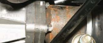
Due to the increased temperature inside the engine compartment, there are cases of deformation of the plastic fan casings, and when they are turned on, the rotating fan blades touch the casing. As a result, the tips of the blades are heated to their melting temperature. When the fans are turned off, the blades are welded to the casing and the next time they are turned on they will not work.
Another possible problem is that the fans start working immediately after the ignition is turned on, when the antifreeze in the engine cooling system is still cold. This happens for the following reasons:
- loss of contact on the block or in the wiring harness going from the coolant temperature sensor to the ECM, because if you remove the connector from this sensor, then if the electrical circuits of the fans are working, they should both work;
- “glitch” (malfunction) of the ECM controller;
- sticking contacts of the fan relay (but the likelihood of sticking contacts on three relays at once is very small);
About miscellaneous...
Rules of communication in the forum
Before you ask a question! How to correctly ask questions in the forum and use site materials.| Moscow time 18:38:33 | Your local time | Vladivostok time 01:38:33 |
| Author: Nortfull (5.141.213.—) Date: 22-09-15 04:18 Colleagues, I ask for help again! There is a book on repairing the Sheva Niva, there are all the diagrams, even how to check the generator using an oscilloscope. It is written about the fans that they do not require maintenance, and that’s it! Tell me where to look for something, maybe a diagram? Last time on the forum they immediately identified the cause of the cabin fan and there was no need for a diagram. Thanks in advance! |
| Author: Glot (185.82.177.—) Date: 22-09-15 04:19 First, short-circuit the wires that go to the radiator, if it works, then change the sensor. True, I don’t remember exactly whether it has a sensor on the radiator or on the engine. |
| Author: s494 (89.179.219.—) Date: 22-09-15 04:44 Northfull wrote: > Closed; does not work! =======Everyone doesn't work? when applying voltage to each? Drive both motors at the same time. Nonsense. I can't believe it. If the shniva is an injector, then they are controlled by the brain. Go for diagnostics, if this is the case. Because they are turned on through a resistor and separately. And you, it seems to me, cannot connect the “+” and “-” to the wires of each fan yourself. |
| Author: Nortfull (5.141.213.—) Date: 22-09-15 04:49 Yes, it’s not a problem to connect, you can install a relay and use your brains. Well, I think that after the brains there should be a relay and a fuse. |
| Author: Borno (5.18.155.—) Date: 09/22/15 04:52 Remove the connector from the second overheat sensor!!! Don't close it, but remove it! The fans should start working at the second rotation speed. Unscrew the sensor, change it, clean the place where it enters the block. (dirt and foam sticks there). Well, first check the relays and fuses (the unit is in the PASSENGER’s feet). I eat oysters on the third Shevik.-)) |
| Author: Nortfull (5.141.213.—) Date: 22-09-15 04:54 Grigorievich wrote: > Remove the connector from the second overheating sensor!!! > Don't close it, but remove it! > The fans should start working at the second rotation speed. > Unscrew the sensor, change it, clean the place where it enters the block. > (dirt and foam sticks there). > Well, first check the relays and fuses (the unit is in the PASSENGER’s feet). > I eat oysters on the third Shevik.-)) Got it. I'll try, thanks already. |
| Author: Nortfull (5.141.213.—) Date: 22-09-15 04:58 Northfull wrote: > Grigorievich wrote: > > > Remove the connector from the second overheating sensor!!! quoted1 > > Do not short-circuit, but remove! > > The fans should start working at the second rotation speed. Where is the second sensor? I have one in the middle of the radiator. filmed doesn't work. |
| Author: s494 (89.179.219.—) Date: 22-09-15 05:01 Surely... you should go to an electrician for diagnostics. I don't know, maybe something shorted out in you or there was a surge in the voltage... and the signal began to be given by Moscow when it was much more than a hundred. And the diagnostician will give you 95-96, and everything will be fine. To be honest, although I understand little about auto electrics, I still go to a diagnostician. At the same time, he will check the entire engine in the winter, you will know what and how. |
| Author: Borno (5.18.155.—) Date: 09/22/15 05:01 Top on the block, under the thick pipe. The connector is directed towards the right headlight. |
| Author: s494 (89.179.219.—) Date: 09/22/15 05:03 There should be two sensors on the engine, one shows the temperature on the dashboard, the other sends the temperature to the brain. |
| Author: Nortfull (5.141.213.—) Date: 22-09-15 05:05 s494 wrote: > No wonder... you should go to an electrician for diagnostics. > I don't know, maybe something shorted out in you or there was a surge in the voltage... and the signal began > to be given when it was much more than a hundred. There was a problem with the generator, three tablets burned out from 12 to 18 volts. The US has posted a new generator. |
| Author: Nortfull (5.141.213.—) Date: 09/22/15 05:09 Tomorrow I’ll find and check the fuses and relays. What needs to be taken apart, where should I look? |
| Author: s494 (89.179.219.—) Date: 22-09-15 05:10 Northfull wrote: > s494 wrote: > > > Surely... you should go to an electrician for diagnostics. > > I don't know, maybe something shorted out in you or there was a surge in the voltage... and the signal > began > > to be given when it was much more than a hundred. > There was a problem with the generator, three tablets burned out from 12 to 18 volts. USA new > generator posted. ======= Didn’t you go for computer diagnostics after that? Well, here's the possibility of a malfunction! It can eat more now, and the lead will go astray... and anything else that the computer manages. |
| Author: Nortfull (5.141.213.—) Date: 09/22/15 05:18 Where do you live? Where am I? I'm afraid of these home-grown car mechanics like hell. It’s better to do it yourself, with your own hands. My neighbor in the garage had a damaged engine, sent it in for repairs, it took a month and a half to repair it, he already put in 20 thousand, in short, the US tells him he needs a new engine. and the shniva drove only 65 thousand. , |
| Author: Nortfull (5.141.213.—) Date: 22-09-15 05:24 I also have a bitter experience; - I gave the hydraulic tensioner to change, after which the oil was squeezed out of the engine (not cheap) and the vibration control stopped working. |
| Author: s494 (89.179.219.—) Date: 22-09-15 05:30
|
| Author: Nortfull (5.141.213.—) Date: 22-09-15 05:30 Grigorievich wrote: > I eat oysters on the third Shevik.-)) Grigorievich Please tell me about the chain, I can’t get rid of the clattering of the chain, it makes a clatter, then it doesn’t, with periods, I changed the tensioner 2 times, well, it doesn’t make a clatter for a month, then again I’ve driven about 50 thousand , what is the problem, is it in the chain or tensioners or such spare parts? |
| Author: Nortfull (5.141.213.—) Date: 22-09-15 05:37 s494 wrote: > Well then, the alternative is to look for relays and supply voltage from a sensor installed > in the radiator or from a switch to the panel. > > The sensor can be installed in a pipe inserted into the cut in the upper radiator hose... > But this is a collective farm of collective farms... I already thought about this, our winter is so severe, the fans can never turn on during the winter, the radiator is wrapped in odil, the engine is covered with It’s cold, but other times I go fishing in the snow from my waist up, and they don’t subside there, they work all the way. |
| Author: s494 (89.179.219.—) Date: 22-09-15 06:30 Our diagnostics of the sov-injector costs 500 rubles. They tell you everything about the engine, they even calculate the wear of the timing belt (on 14k). |
| Author: Slavyanin (—.broadband.corbina.ru) Date: 09/22/15 06:49 I very much doubt that the vehicle’s program or settings have gone wrong. I’m curious about the belt, what’s being calculated? And it will probably depend on the controller. |
| Author: s494 (89.179.219.—) Date: 09/22/15 07:01 By opening the valves, probably... I don’t know. Maybe they hit my ears. But the belt really had a real problem. |
| Author: PUKH (37.79.248.—) Date: 09/22/15 08:54 Check the fuses and relays, located at the feet of the right front passenger, under the glove compartment. When you remove the block from the T sensor, which gives a signal to the brain, both Carlsons are triggered (do this first). As for the hydraulic timing chain tensioner - throw it out and install an automatic timing chain tensioner - “Isay” |
| Author: Judge Dredd (78.25.120.—) Date: 22-09-15 09:04 Somehow I didn’t touch on this point... According to the diagram above, there is only one temperature sensor, it should be located somewhere in the cylinder head area... About what sensor on are we talking about the radiator???... |
| Author: PUKH (37.79.248.—) Date: 22-09-15 15:42 Temperature sensors on the engine - 2 pcs. One is located above the spark plugs of 3-4 cylinders, 1 wire fits, works for the device on the panel - we don’t need it . The second one is located next to the thermostat, 2 wires fit, this is what you need, see the link under No. 1, when you remove the block from it, the computer sees an error and turns on both Carlsons = start by removing the connector from this sensor. Link. |
| Author: Alexander Kst (—.176.59.117.243.tele2.ru) Date: 22-09-15 15:57 The clatter of the chain on classic chain engines cannot be eliminated for a long time by replacing the same chain or tensioner. It is necessary to change the sprockets along with the chain. Old sprockets roll a new chain 500 km away. |
| Author: Bubble67 (Vesely Poselok) (—.broadband.corbina.ru) Date: 22-09-15 16:10 On the last five-door car, which has electrics similar to Shniva, I neutered the standard system, cut a tee into the upper pipe and screwed it into it fan switch sensor from Audi-80. It has exactly the same thread as our large one from 03, but controls two fans, turning them on in series. A tee for a sensor of this type is sold freely. Power is supplied directly from the battery through a separate 30A fuse. And this not a collective farm of collective farms, but the simplest one, respectively. efficient and reliable design. |
| Author: SAA (—.ve.mrsk-yuga.ru) Date: 22-09-15 16:24 To prevent the chain from chattering, keep the oil level at the maximum mark, but it is better to install a mechanical automatic tensioner. |
| Author: Nortfull (213.87.240.—) Date: 22-09-15 16:51 POOH wrote: > Temperature sensors on the engine - 2 pcs > One is located above the spark plugs of 3-4 cylinders, 1 wire fits, works for the device > on the panel - we don’t need it. > The second one is located next to the thermostat, 2 wires fit, this is what you need, see the link > under No. 1, when you remove the block from it, the computer sees an error and turns on both Carlsons > = start by removing the connector from this sensor. > Link. I removed the sensor, it hissed something, but the fans did not turn on, I disassembled the glove compartment and found the block relay, the fuses were intact. |
| Author: Nortfull (213.87.240.—) Date: 22-09-15 17:22 It looks like something with a resistor was applied to the relay control terminal - the first vent. They didn’t spin on the second and the third worked. Where is the resistor located? |
| Author: PUKH (5.141.193.—) Date: 22-09-15 17:29 It is not the sensor that needs to be removed, but the connector from it. ……..Up on the block, under the thick pipe. The connector is directed towards the right headlight.... There are no sensors on the radiator or you already have a lot of them. |
| Author: Nortfull (5.141.215.—) Date: 22-09-15 20:13 Judge Dredd wrote: > On the casing, between two fans... And I thought it was a sensor. Thanks, I'll go spin it now. [email protected] #$%^sky tablet inserts its own words. |
| Author: Nortfull (213.87.240.—) Date: 22-09-15 21:25 Yes, they don’t have a 7 Ohm resistor, that’s normal. I removed nothing from the thermostat sensor. It turns out that the first relay is constantly on, the second turns on the non-pump, the second and third fans. |
| Author: Nortfull (213.87.240.—) Date: 22-09-15 21:40 I found the low speed relay for the right fan, it is separate, the signal was sent, it worked, now it turns out there is no signal coming out of the brain? |
| Author: Simple (217.118.93.—) Date: 22-09-15 21:47 Listen to POOH, he wrote correctly, the fuses are under the glove compartment. There's a healthy red one there, most likely it. |
| Author: Nortfull (213.87.240.—) Date: 22-09-15 21:58 Does it protect the living ones, the fans are working, there is no signal for the fan relay to be turned on. |
| Author: Judge Dredd (78.25.120.—) Date: 22-09-15 22:11 I hope that you perform all actions with the ignition on, or even better with the engine running???... For even with the ignition simply on, but Without a signal about the motor running, the control unit may not issue a command to turn on the fans... |
| Author: Nortfull (213.87.240.—) Date: 22-09-15 22:24 The ignition is on! It should work without the engine running, I'll try to start it now. |
| Author: Nortfull (213.87.240.—) Date: 22-09-15 22:35 Judge Dredd wrote: > Because even with the ignition simply turned on but without a signal about the engine running, the > control unit may not issue a command to turn on the fans... The main motor started working, but the motor started up. Well, thank you! All that remains is to check the sensor, the question is: how? |
| Author: Nortfull (213.87.240.—) Date: 22-09-15 22:38 I went to collect the glove compartment, but it was raining outside, and my favorite boat was in the garage, unlucky for the cars. |
| Author: Judge Dredd (78.25.120.—) Date: 09/22/15 22:53 Northfull wrote: > The sensor remains > to be checked, the question is: how? ======================= Well, if you’re in the garage and on your knees, then you stupidly warm up the engine and watch the temperature gauge so as not to boil, and monitor the turning on of the fans... If they don’t turn on consistently, or turn on late, change the sensor... |
| Author: Nortfull (213.87.240.—) Date: 22-09-15 23:05 I disassembled another unit in the Chevy with my own hands, practically only one motor and a front gearbox remained. And then I already sorted everything out. |
| Author: PUKH (5.141.194.—) Date: 09/22/15 23:36 So your propellers didn’t work, maybe simply because the motor didn’t heat up. T sensor above spark plug 4 cyl. Maybe he’s lying and the temperature on the panel is wrong, tighten the terminal on it, in your mind you need to go to the diagnostics, then run both Carlsons from the computer and look at the T of the screws working on the computer (software) and in fact. |
| Author: Nortfull (213.87.240.—) Date: 23-09-15 01:01 POOH wrote: > So your propellers did not work, maybe simply because the motor did not heat up. > T sensor above spark plug 4 cyl. maybe he’s lying and the temperature on the panel is wrong, > tighten the terminal on it, in your mind you need to do diagnostics, then run both > Carlson from the computer and see the T of the screws working on the computer (programmatically) and in fact. Yes, we need to stop by, first we need to find where we have this diagnostic. Thank you. |
| Author: Nortfull (5.141.20.—) Date: 25-10-15 22:31 And Shniva has become again! The fuel pump, which I had already successfully replaced, does not work, but no such luck, it turns out the “+” does not come. It’s already happened three times before, I couldn’t start it, it would sit and then work, but no way. The fuel pump relay works, “+” goes away, but does not come. Please tell me! Where to see? |
| Author: Judge Dredd (78.25.120.—) Date: 25-10-15 22:48 Well, it’s not very difficult either... If the power goes out from the relay (note that after turning on the ignition this lasts a few seconds), and to the pump doesn’t reach, then you need to look for a break/bad contact... Sometimes it’s easier to throw in a new wire without bothering... |
| Author: Nortfull (5.141.20.—) Date: 25-10-15 23:21 I bought a wire, but I’m interested in where is the break? Maybe the signal is old, I installed a new one and blocked the starter. |
| Author: Judge Dredd (78.25.120.—) Date: 25-10-15 23:41 Well, if you are interested, look for it...)) Looks like you have the diagram, look at how the wire goes... Relay/fuse/mounting block... Where then it moved away/rotted... The exact location cannot be determined from the tilipon.... |
| Author: Nortfull (5.141.21.—) Date: 26-10-15 03:14 Tell me, who knows where to look for the connector block, according to some diagrams No. 30-31, it seems to me that all the fuss is there! |
| Author: Judge Dredd (78.25.120.—) Date: 26-10-15 03:57 Either I’m blind, or the screen on the laptop is small, or the quality of the picture is such that I can’t even distinguish all the numbers in the circles... (( But it seems to me that the connector you need is in the mounting block... It makes sense to *screw* everything there, perhaps contact will be restored... |
| Author: s494 (89.179.23.—) Date: 26-10-15 06:12 Was: you turn on the ignition, the motor in the tank hummed, after five seconds it chimed and turned off? Look where there was a click when turning it off. |
| Author: s494 (89.179.23.—) Date: 26-10-15 06:22 Yes, Tolya, I didn’t read it. (Well, connect the wire “+” going from the relay to the motor. |
| Author: Nortfull (5.141.20.—) Date: 26-10-15 06:46 s494 wrote: > Yes, Tolya, I didn’t read it. ( > Well, connect the wire “+” going from the relay to the motor. I want to do that, as a backup option, but I want to find the problem. |
| Author: Nortfull (5.141.214.—) Date: 26-10-15 17:53 I connected the fuel pump directly and the car does not start. I found a melted lambda sensor connector. |
| Author: Nortfull (5.141.20.—) Date: 27-10-15 20:00
|
| Author: Judge Dredd (188.168.252.—) Date: 28-10-15 01:47 Somehow your repairs are going in the wrong direction...(The other day there was only a broken wire to the pump, now everything has gone out and burned out... I’m afraid that it’s impossible to do without a *specially trained person* on site... |
| Author: Nortfull (37.79.109.—) Date: 28-10-15 02:59 I found a “jamb”, there was no contact in the controller connector, I soldered the wire, oh, luckily, it started. |
| Author: Nortfull (37.79.109.—) Date: 28-10-15 04:08 Judge Dredd wrote: > Well, okay... ) > As I understand it, the relay initially did not work, although you wrote the opposite... I apologize, I confused the relay, I screwed myself and people. I can’t understand why the oxygen sensor connector melted, maybe it fell on the manifold from the previous owner, the car is 2003. |
| Author: Nortfull (5.141.214.—) Date: 28-10-15 20:30
|
| Author: Judge Dredd (188.168.252.—) Date: 29-10-15 02:10 Northfull wrote: > installed the boiler for one thing, follow but > “Vibasto”, included the “Vibasto” pump in the circuit, installed a small charger > device. ============================= Can't get through the text...( |
| Author: Nortfull (5.141.214.—) Date: 29-10-15 03:11
> Nortfull wrote: > > > installed the boiler for one thing, follow the > > “Vibasto”, included the “Vibasto” pump in the circuit, installed a small charger > > device. > ============================ > I can’t comprehend the text...(I’ll attach a photo here, maybe it’ll be clearer this way: |
| Author: Nortfull (5.141.214.—) Date: 29-10-15 03:25
> USA drew it, now you can heat the car with either a Vibasto or an electric boiler. not sticky: |
| Author: Nortfull (213.87.248.—) Date: 30-10-15 00:00 Just looked at their website for boilers that are 50 rubles more expensive than ours in the store. I wonder why the official one is more expensive than the regular one here too? |
| Author: s494 (—.broadband.corbina.ru) Date: 30-10-15 02:29 Not about boilers. Do you have enough battery charge on your generator? I put Link in the winter. . Of course, our winters are not cold, but you measure the voltage with a tester when the engine is running, it seems 13.6 volts. You turn on the headlights - 13.4. Few. Now without consumers there is 14.6 volts, you turn on the stove and headlights 14.4 volts. More interesting. I used to solder a diode into the gene, but now I have stopped. This thing that I just installed has adjustment. In summer you can change the voltage. Installation takes 10 minutes, no need to remove the gene. Price 390 rubles in the magician. |
| Author: Nortfull (5.141.21.—) Date: 30-10-15 03:15 Interesting topic, should I try it on? Last year the battery began to run low, I replaced it and this one started to lose its mind, it turned out that the car had problems with the generator, I replaced two regulators and nothing helped. By the way, on mine the generator is (when viewed from the front) on the left. I spat, bought a new one, the guy suggested, it’s 300 more, but it gives out -120A (China) instead of 80A. I installed it and everything is fine, there are no drawdowns, everything is smooth, but the battery is already dying. There is a gel 60A, but it is larger, it sits on the metal without a stand. and the launcher is small. |
| Author: s494 (—.broadband.corbina.ru) Date: 30-10-15 03:23 On Shniva gene 9402.3701-01 I have one too. I installed the regulator for him. Second from top by Link. |
Circuit breakers
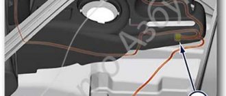
The electrical circuits of Niva Chevrolet cars produced before and after 2009 are different. In both cases, 50-amp fuses protecting the electric fan power circuits are located in an additional unit. It is located behind the glove box on the passenger side of the cabin. The figure shows where the fan fuses are located.
If the permissible current is exceeded, the insert melts and the circuit opens. Therefore, fuses are the first thing to check if the electric cooling fan does not work. The performance of a part can be assessed visually or using an ohmmeter (multimeter). To do this, you will first have to remove the fuse from the socket.
Main block with fuses and relays
This block is located to the left of the steering column and is closed from below with a lid. To get to it, you need to tighten 2 screws, then press the top edge of the cover and gradually free it from all fasteners.
The block that appears will be held on a special bracket. The fuse diagram itself and the number of elements on it may vary depending on the configuration and year of manufacture.
Also interesting: What you need to know about the VAZ 21214 engine before buying a Niva | Weak engine
photo of the fuse box in a Chevrolet Niva
Power sensor
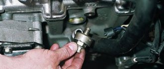
The control unit receives information about the antifreeze temperature from a temperature sensor. It is a resistor whose resistance changes with heating and cooling: from 1.3-1.8 kOhm at 30℃ to 155-196 Ohm at 90℃. You can check its performance using an ohmmeter and a thermometer. To do this, you need to remove the part, immerse it in water and measure the resistance at different temperatures.
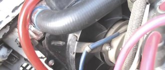
The sensor is located on the engine head in the area of the exhaust pipe of the cooling system. You can unscrew it with a socket or socket wrench.
We recommend watching a video that shows where the sensor is located and how to check:
Possible malfunctions and their causes
1.Both fans do not work. The electric motors may fail, the temperature sensor may malfunction, or the power wires coming from the battery or ignition switch may be broken.
2. The second fan does not work. Causes: sensor malfunction, fuse or electromagnetic relay failure. It is also possible that the power cable may be broken.
3. The left fan does not turn on. Causes: faulty power resistor or temperature sensor, blown fuse or relay. It is also possible that the power cable may be broken.
4. Only two fans turn on at a time. This happens when an additional resistor in the circuit of the first electric motor breaks.
5. The fan does not turn off. Typically, the fan runs constantly when the relay is broken or the coolant temperature sensor is faulty.
Repair of fans, sensor, relays, fuses and additional resistor is not provided. If these parts break, they should be replaced with new ones.
Pump failure
A pump is a water pump that is necessary to circulate coolant throughout the system. The pump on the Niva is driven by a drive belt. If the belt breaks, the engine will not only be left without cooling, but will also lose charge from the generator.
But the pump fails not only because of the belt. The main reason for the breakdown of the water pump on the Niva is the breakdown of the impeller. As a result, circulation is disrupted and the engine begins to heat up at idle speed. When the speed increases, the engine may cool down.
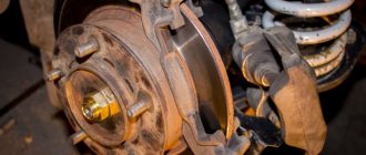
Brakes
Brake pads, Drum pads, Pad wear sensor, Pad repair kit, Pad spacer, Rear pads, Handbrake pads, Front pads, Brake linings, Brake discs, Rear brake discs, Front brake discs, Brake drum, Rear brake drum, Drum bearing, Brake hoses, Brake pipes, Brake caliper, Caliper repair kit, Rear caliper, Caliper guides, Front caliper, Caliper piston, Caliper boot, Caliper bracket, Hydraulic accumulator, Vacuum brake booster, ABS, ABS unit, ABS sensor, Vacuum pump, Brake pedal, Switch Brake Light, Air Brakes, Parking Brake, Handbrake Cable, Brake Cylinder, Master Cylinder, Brake Reservoir, Brake Service Cylinder, Rear Brake Cylinder, Front Brake Cylinder, Brake Cylinder Repair Kit
Rules for operating a car if a problem takes you by surprise
If the cooling fans stop working, then you need to follow some rules to prevent the engine from overheating:
- Enable forced operation of the fan from the battery. If this does not help, go to step 2.
- Limit your driving speed to 60 km/h and try to maintain this speed constant. This will allow you to cool the antifreeze without a radiator.
- If possible, resort to heating the interior, this will remove some of the heat from the coolant.
- If possible, stop while driving; this will also remove heat from the antifreeze.
Replacing fans
If the fan motors do not start when the wires from the battery are connected directly to the power terminals, the devices must be replaced.
To do this, you will need a set of wrenches ranging in size from 10 to 17 mm and a Phillips screwdriver.
Before starting work, you need to drive the car onto an inspection ditch or a lift and turn off the power to the on-board network by removing the negative terminal of the battery.
Fans are dismantled as follows:
- Remove the crankcase protection and mud guard.
- Unscrew the screws and remove the thick spider-shaped plate and a couple of tin covers that are located in front under the bottom of the car.
- Unscrew the radiator frame cross member.
- Loosen the tension and remove the power steering belt and pump.
- Remove the 4 bolts holding the power steering pump.
Useful video showing how to remove and change fans:
Important: to get to the bolt covered by the oil filter, you need to move the amplifier away from the bracket.
- Push the pump back, hanging it on the hoses.
- Remove the air conditioner drive belt.
- Remove the bolt holding the timing belt pulley.
- Remove the pulley and belt.
- Unscrew the four nuts at the corners of the electric fan housing and the two bolts securing it in the middle.
- Remove the fan unit from the studs and pull it down.
Tip: The crankshaft position sensor makes it difficult to remove the fans. Therefore, they need to be pulled out gradually. The left side is lowered first, then the block is moved to the left, raising the right edge so that the casing becomes vertical.
This method is probably suitable for restyled Niva Chevrolet models. On older cars, you will have to remove the radiator grille and bumper, unscrew the fasteners and move the air conditioning and cooling radiators forward. After this, access to the electric fans will be open.
During dismantling, you should carefully remember the procedure. Assembly is carried out in reverse order.
Important: the service life of the fan motors is approximately the same. Therefore, even if one of them fails, both must be replaced. Otherwise, you will soon have to repair the car again.
Checking and removing fans
To understand whether they work or not, you need to disconnect the connector from their motors, and connect a lamp to the wires through which voltage is supplied; we do the same with the sensor; if both lamps light up, then the problem is in the fans.
To remove them you need to do the following:
- Disconnect all wires
- Removing the upper pipe
- Removing the bumper
- If there is an air conditioner, bend the tubes (this must be done carefully, as they may burst) or drain the freon (filling it back will not be cheap), then remove the air conditioner radiator.
- You need to loosen the nuts on the radiator casing
- Tilt the radiator so that you can remove the fan unit
- Unscrew the bolts that secure the block and remove it
After removal, it is recommended to immediately replace both with new ones, since there is a possibility that a little time will pass and the second element will fail and all replacement work will need to be done again. You can do this procedure from below, but you will need special equipment, and you will need to move the engine ten centimeters back, which is very labor-intensive.
engine temperature
engine temperature
Post by pavel62 » 08 Mar 2014, 08:12
Re: engine temperature
Post by Sash » Mar 08, 2014 10:54 am
Re: engine temperature
Post by pavel62 » Mar 08, 2014, 11:46 am
[quote=”Sash”]I don’t know how it was before, but in the fields at the end of 2013. both fans turn on at 98 degrees. I installed the BC, and through it (there is a function called “tropical temperature”) I set one fan to turn on at 95 degrees. Now, when it reaches 95 degrees, one fan turns on - there is less noise, the voltage in the car’s network also does not sags as with two fans.[/quote
I have a Niva M 2014, (both fans turn on at 98 degrees), that’s right... How can I set up this mode?
Re: engine temperature
Post by ParaLanik » Mar 08, 2014, 11:51 am
How I did it. I have leg No. 29 on a Bosch ECU 7.9.7+, empty. Having set the “tropic” to 97 degrees, 2 vents still turn on (for leg No. 68). Of course, I was perverted and did it (this is a separate topic). I'm asking if you have a simpler solution.
And after adjusting the Tropic, I stopped, turned off the engine, turned off the ignition - and the fan runs until the temperature drops
- without the tropic there is no such thing. I turned off the engine and the fan was cut off.
Source
Separate activation of fans on Niva
On the Niva car, unlike the Chevrolet Niva, the designers did not complicate production and made sure that the two cooling system fans (VCO) always operate at full power, when it is needed and when it is not needed. At the same time, the Bosch 7.9.7 control unit has an output for controlling the second fan. And with a little modification to the wiring, you can make the car more economical, and not frighten those around you with the howl of two simultaneously turning on fans, when one would be enough.
Test vehicle Niva 2131, 1700 cm3, manufactured in 2007. Bosch controller 7.9.7. Software B120EQ16. Euro2.
Task: Connect two-stage VSO control. When reaching the first temperature level, so that they work slowly, and at the second level - at maximum performance.
Accordingly, when turning on the first level, it was decided not to install additional. resistors, but simply turn on two fans in series. With this scheme, at the first level we have lower power consumption, as a result, fuel savings, lower noise levels, and both fans always rotate together. It is important that they wear evenly.
In a parallel circuit, we have greater wear on one of the fans. After winter, the second fan may not turn on due to the fact that its services have not been needed for a long time and it simply “sours.”
To begin with, we drew a connection diagram. I had to add a third relay.
29 there is no ECU output in the Niva braid. We disassemble the ECU connector and insert a chip with a wire into pin 29. Now we need to modify the ECU itself. In the factory firmware, the temperature for turning on fan 2 is 120 degrees.
Using the editor, we adjust the switching temperature of fan relays 1 and 2.
We lower the turn-on temperature of the first stage of cooling to the range of 97-95 degrees Celsius (on and off, respectively). And we set the range of maximum VSO performance to 99-96 degrees (on-off).
Next, using the programmer, we load the modified firmware into the ECU. Let's put everything back in place. We start it up, connect the scanner and check what we got.
When checking, it was discovered that when the fans on the second level are turned on, they operate intermittently. Those. The relays close for about 3 seconds, then open for three seconds, and so on cyclically until the temperature drops below the set level. The problem is in the factory firmware software for the Niva. The solution to this problem is to replace the software with B122HR91 (2 Serial version for the new hardware implementation on the Niva - Chevrolet), with the replacement of the corresponding calibrations. Which is what was done.
In the finished version, when the cooling temperature reaches 97 degrees, the first VCO stage is turned on, two fans operate at half power. In most cases, this is enough to lower the temperature in a traffic jam or when parked. There is no sound of howling motors, the load is 2 times less, accordingly, fuel consumption is reduced, and fan wear is the same. If for some reason the performance is not enough to cool the motor, then when the temperature rises to 99 degrees, two fans turn on at maximum power.
Before and after modification, I took oscillograms of the fans turning on. The measurements were carried out in the box, with the engine turned off. The voltage on the battery is 12.4V. The fans are in good working order (almost new).
The first oscillogram shows the moment when one fan is turned on and running. Second oscillogram - two fans are switched on in series (moment of switching on and operation).
One fan: Current at the moment of switching on = 61 A, during operation current = 20 A. Two fans are connected in series: Current at the moment of switching on = 26 A, during operation current consumption = 7A.
Design of the Chevrolet Niva 2123 cooling system
Structurally, the 2123 car is similar in design to its predecessor, the Niva 2121. But it is devoid of those shortcomings that appeared during the mass operation of this car. Thus, the new model lost the tap on the stove. For the outflow of coolant, a special hole in the thermostat is now used, which is ensured by the operation of a special damper system.
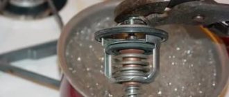
The main difference is a fundamentally new thermostat design.
And the principle of its operation: