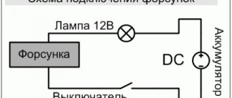
What is a slider with a resistor and what role does it play in the ignition distributor?
A slider with a resistor is a rotor of the ignition distributor of a contact and non-contact ignition system, equipped with an interference suppression resistor.
Any ignition system is a powerful source of radio interference that disrupts the reception of radio programs in all ranges both in the car itself and in vehicles passing nearby. This noise is heard as clicks and crackles, the frequency of which increases with increasing engine speed. Interference is generated by sparks that occur in various parts of the high-voltage circuit of the ignition system: in the spark gaps of the spark plugs and between the contacts in the cover and the distributor slider. When a spark jumps, electromagnetic radiation of a wide spectrum occurs - this is why interference is heard on almost all radio bands. However, the spark itself produces radiation of low intensity; the main power is emitted by components associated with the spark gap - high-voltage wires that act as antennas.
To combat the described phenomenon, additional elements are introduced into the high-voltage circuit of the ignition system - distributed or concentrated resistances. High-voltage wires with non-metallic central cores act as distributed resistances. The resistors in the spark plugs and in the distributor slider act as concentrated resistances—it is this detail that will be discussed further.
Why does introducing a resistor into a high-voltage circuit reduce the noise level? The reason is quite simple. When a breakdown of the spark gap occurs, high-frequency currents run through the conductor connected to it, which leads to the emission of radio waves by this conductor. Placing a resistor with a resistance of several thousand ohms between the spark gap and the conductor changes the picture: together with the capacitances and inductances that conductors always have, a simple filter is formed that cuts off the high-frequency component of the interference. In practice, a complete cut does not occur, but the amplitude of high-frequency currents in the wire decreases sharply, which leads to a multiple decrease in the level of radio interference in the high-voltage circuit of the ignition system.
If we relate all of the above to the distributor runner, then the spark gap here is the contacts of the cover and the contact of the runner passing nearby, and the antennas are the high-voltage wires running from the coil to the runner and from the contacts to the spark plugs. Thus, here the resistor is between two conductors, however, the greatest suppression of interference occurs on the wire from the coil, and suppression of interference on the spark plug wires occurs due to the resistance of the wires themselves and the resistors built into the spark plugs.
That is why this resistor is called noise-suppressing (or simply suppressing). However, in addition to combating radio interference, the resistor also performs several more functions:
- Preventing (or reducing the intensity) burnout of the contacts of the distributor cover and the slider itself;
- Reducing the likelihood of electrical breakdown from other high-voltage sources;
- Increased service life of spark plugs and related components;
- Increasing the duration of the spark discharge, which in some cases increases the stability of the engine.
Why is all this happening? The reason is the resistance to electric current that the resistor creates. Due to the resistance in the high-voltage circuit, the current strength decreases during the discharge - it is enough for the spark between the electrodes of the spark plugs to ignite the combustible mixture, but not enough for the local melting of the metal of the electrodes and contacts in the distributor. In this case, the power stored in the coil remains the same, however, due to the increased resistance of the circuit, it is given to the spark plugs not instantly, but over a certain period of time - this leads to an increase in the discharge time, which ensures more reliable ignition of the mixture in the cylinders.
Thus, just one resistor in the ignition distributor slider performs several functions that increase engine efficiency and vehicle operating comfort.
Checking the module and adjusting the ignition of the VAZ 2107 (injector)
The VAZ 2107 ignition module (injector) is a unit whose malfunctions are quite difficult to diagnose
Problems with the module's operation are noticed only after serious engine malfunctions occur. If the engine does not start, you should try adjusting the ignition
If the engine is running unevenly, a serious check of the functionality of the VAZ 2107 ignition module may be required.
Ignition is an electronic system for converting the low voltage of the vehicle's on-board network into high voltage and supplying the latter to the electrodes of the spark plugs.
Checking the ignition system elements
Misfires in engine operation, especially in wet weather, are a consequence of breakdown of the insulation of high-voltage wires. There should be no cracks or damage in the wire insulation. You can check the insulation for breakdown using a wire connected to ground. If you run it along the insulation while the engine is running, a spark will be observed in places with damaged insulation. Another clear sign of poor insulation is noticeable electric shocks when touching high-voltage wires while the motor is running.
A broken high-voltage wire can be easily determined with an ohmmeter. The resistance should be between 3-10 kOhm. The spread of indicators between the wires should be no more than 1-2 kOhm.
Signs of breakdown
When the ignition is turned on, the engine ECU malfunction indicator light comes on, and after the engine is started, it should go out. A burning warning light is the first sign of problems with the ignition system. Other prerequisites for diagnosing the ignition module are “floating” engine speed and problems with starting. The cause of such failures may be faulty high-voltage wires or spark plugs, so you need to make sure they are working before you start diagnosing the ignition of the VAZ 2107 (injector). Often, cylinder misfires occur due to compression problems or damage to the intake manifold gasket. This must be taken into account when searching for the causes of engine failure.
Preparing for ignition diagnostics
To check the condition of the elements of the ignition system and the module as a whole, you will need a multimeter - a device designed to measure the electrical characteristics of the system (resistance, voltage, current). With its help, you can determine the voltage supplied by the module to the ignition coil, the serviceability of the coil and the reasons for the loss of current in the circuit. To make work easier, the ignition module can be removed externally.
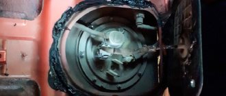
Removing the ignition module VAZ 2107
- Remove the air filter housing.
- Disconnect the negative terminal from the battery.
- Remove the high-voltage wires from the ignition module cover.
- Unscrew the three nuts securing the VAZ 2107 ignition module and disconnect it from the bracket.
Checking the ignition coil
The coil is checked based on two indicators: the presence of a short circuit and an open circuit. Before diagnostics, the ignition coil must be disconnected. After this, one probe of the device is connected to the central contact of the coil, the second to the body (ground). If the display shows resistance equal to infinity, there is no short circuit.
The primary winding of the coil for a break occurs differently. The probes of the device must be connected to the right and left contacts. The resistance between them should be within 3-3.5 Ohms.
If the resistance of the primary winding does not correspond to the norm or there is a short circuit in the coil to the housing, it must be replaced.
Ignition adjustment
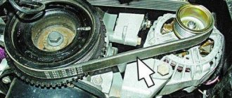
The injection modification of the VAZ 2107 does not require adjustment of the ignition timing. The electronic control unit, using a sensor, determines the optimal ignition timing. The participation of the car owner in adjusting the operation is limited to setting the engine timing belt to the marks.
To check the performance of the ECU and the functionality of the sensors, it is necessary to connect a computer with specialized software. In this way, the cause of most electronic ignition system malfunctions can be determined.
It is also worth checking the operation of the throttle position sensor yourself. When the throttle is closed, the voltage on the sensor should be no higher than 0.55 volts, and when fully open - 4.5 volts. Measurements must be made with a voltmeter with the ignition on.
Design and characteristics of a slider with a resistor
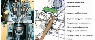
The slider (rotor) with a resistor consists of several parts: a cast body, two rigidly fixed contacts (central, resting on a corner in the distributor cover, and a side one) and a cylindrical resistor located in a special recess. The housing is made of electrically insulating material; the contacts are usually fixed to it using rivets. The contacts have spring plates, between which a resistor is clamped. In the lower part of the slider body there is a shaped channel for fixation on the ignition distributor shaft.
According to the method of installing the resistor, there are two types of sliders:
- With replaceable resistor;
- With a non-replaceable resistor - the part is filled in a recess with a special insulating compound based on epoxy resin or glassy materials.
The runners use powerful resistors of a special design with end leads, designed for installation between spring contacts. In domestic cars, resistors with a resistance of 5.6 kOhm are most often used, but in various sliders you can find resistors with a resistance of 5 to 12 kOhm.
Depending on the type of distributor, the slider can be simply mounted on the distributor shaft (usually such parts are T-shaped), or mounted with two screws on the ignition timing regulator (such parts are made in the form of a flat cylinder). In both cases, the resistor is mounted on the outside of the slider, which allows access to its inspection and, if possible, replacement.
Which distributor is suitable for the VAZ-2107
On all carburetor rear-wheel drive VAZ cars, the device has almost identical components and a similar operating principle. Distributors for engines with a volume of 1200-1300 cc differ in that: – the drive rod is 7 mm shorter; – no vacuum ignition timing regulator; – the settings of the weights and springs of the centrifugal regulator are different. For engines with a volume of 1500-1600 cc, all distributors are suitable in terms of mounting dimensions and characteristics. Only “Nivovskie” ones differ. They are tuned for stable traction at low speeds and the VAZ-2107 with such a distributor will accelerate slowly. The brands of “Nivovsky” distributors are: 3810.3706, 038.3706-10. And distributors of brands 0.3706 (contact) and 38.3706 (non-contact) are suitable for the “Seven” and other classic cars.
Read, it may come in handy: Useful improvements to your “seven”
Questions about choosing and replacing a slider with a resistor
A slider with a resistor filled with compound. A replacement resistor for the slider.
The resistor placed in the slider is subjected to significant electrical and mechanical loads, so over time it can fail - burn out or break (crack). As a rule, a breakdown of the resistor does not disable the engine, but seriously impairs its functioning - the engine does not gain full power, responds poorly to the gas pedal, “troits”, detonates, etc. The fact is that sparks can jump through a burnt out or cracked resistor, so the ignition system continues to work, but with disturbances and less efficiently. If such signs appear, you should first remove the distributor cover (this should only be done with the engine stopped and the terminal removed from the battery), dismantle and inspect the slider. If the slider is ordinary, then it can be removed without a tool, and if the part is connected to the ignition timing regulator, then two screws should be removed using a screwdriver.
If, when examining the resistor, there are no external signs of its malfunction (it is not burnt or broken), or the resistor is filled with compound, then you should check its resistance using a tester - it should be within 5-6 kOhm (for some cars - up to 12 kOhm, but not lower than 5 kOhm). If the resistance tends to infinity, then the resistor is faulty and should be replaced. A replacement part should be of the same type and resistance - this is the only way to guarantee that the resistor will fall into place and the entire system will work normally. Replacing a resistor involves simply removing the old part (it’s easy to pry it off with a screwdriver) and installing a new one. If the resistor is filled with compound, then you will have to change the entire slider - for domestic cars such a replacement will cost several tens of rubles.
Often, car owners install wire jumpers instead of resistors - this is strictly prohibited. The absence of a resistor increases the level of radio interference and can disrupt the operation of the ignition system (including leading to intensive wear of the contacts of the slider and distributor cover, and spark plug electrodes). It is also not recommended to replace a slider with a resistor with a simple slider in ignition systems with high-voltage wires of zero resistance. For replacement, only those types and models of runners recommended by the ignition distributor manufacturer should be used.
Occurring faults
The design of the lock is quite simple and reliable, but the lock may well break. There are only two malfunctions that can happen to this element: mechanical and electrical.
A mechanical failure includes a problem with the secretion. Due to debris that gets inside the secretion and moisture, corrosion is formed, which prevents the movement of moving elements inside the secretion. As a result, the lock begins to jam when you turn the key, jams, or stops rotating altogether. This problem can be eliminated by pouring WD-40 or at least brake fluid inside. However, if it is possible to restore the functionality of the secret in this way, it will not be for long. The secret itself is not repairable, and in the event of such a malfunction, the VAZ-2101 ignition switch will eventually need to be replaced.
An electrical fault is the burning of the nickels of the contact group. Because of this, there will be no or insufficient contact between the runner and the nickel. Electrical appliances on the car will not work, and there may be no power supply to the starter. If the burning was minor, then you can try to restore the functionality of the lock by cleaning the nickels with a diamond file, followed by wiping with alcohol or gasoline. But if the nickels are badly burnt, then you will need to either change the contact group or the lock assembly.
An interesting article about biofuel produced from ordinary sawdust, read more here.
Distributor malfunctions and how to fix them yourself
For many car owners, the issue of reliable and quick engine starting is one of the priorities. And an important role in this is played by the ignition distributor-distributor or distributor. The impossibility of normal operation of the motor is largely due to problems with the breaker. In what cases is the distributor repaired and diagnosed and how to repair it yourself - read this article.
Why turn on the ignition?
The ignition circuit includes several main elements - a VAZ ignition switch, a distributor, spark plugs, and high-voltage wires. Before you set up the distributor and set the contactless ignition of the VAZ (BSZ), you need to understand the consequences of its incorrect setting. Before adjusting the device, you need to make sure that the problem does not lie in the distributor, spark plugs or wire connections, since their symptoms are similar.
Installation of a contactless device is carried out with the following symptoms:
- Detonation. When the engine is running, metallic sounds are heard from under the hood.
- Engine power and speed have decreased significantly.
- The power unit as a whole does not operate steadily at low speeds.
- Fuel consumption will increase.
- In addition, if the distributor is set to late ignition, this can lead to engine overheating.
With these symptoms, a large amount of deposits and soot will form on the engine walls, and wear on the components of the power unit will also increase.
Purpose of the mechanism
Before we tell you how a faulty distributor should be checked to identify breakdowns, let’s look at the purpose of the device. The breaker is a unit designed to detect the moment of formation of high-voltage signals in the system. The distributor is installed on both carburetors and injectors, and this mechanism is used to distribute electric ignition among the engine cylinders. That is why many car owners are interested in the question of how to set the ignition and adjust the distributor, where to turn it - this is necessary for the normal operation of the power unit.
In its design, this mechanism differs from others in the presence of various elements in the structure, which tend to wear out over time. When the first signs of malfunctions in the operation of the distributor are identified, the device must be removed and repaired, since its condition largely determines the operation of the power unit and its characteristics.
In addition to setting the ignition, the distributor performs the following functions:
- interrupts the primary ignition circuit, which ensures the appearance of a high-voltage pulse;
- distributes the spark among the cylinder spark plugs in a certain sequence.
Breaker device design
How to set the ignition on a VAZ 2106
The operation of setting the ignition is one of the most important, like everything that concerns the engine as a whole. Starting the engine, as well as its actual operation, depends on the correct setting of the ignition. And consequently – fuel consumption, safety, and engine performance.
Most motorists, when it comes to the engine, prefer to delegate authority to car service specialists. This is a worthy solution, although absolutely anyone can learn how to set the ignition (as well as carry out other diagnostic, repair and other operations). To do this, just do it a couple of times in your VAZ.
Tools needed to set the ignition at home and garage:
- spark plug key;
- key to 13;
- voltmeter (or 12 volt light bulb).
When working with a VAZ 2106, the ignition can be set in two ways - on the 1st or 4th cylinder. The most common is the first option, and we will consider it.
There are three marks on the timing cover - long, medium and short. These marks are of fundamental importance for setting the ignition. The long one corresponds to a lead angle of zero degrees, the medium one is 5 degrees, the short one is 10 degrees. In addition to these marks, there is also a top dead center, indicated on the pulley rim and duplicated opposite by a bead on the pulley hub.
Symptoms of a problem
Of course, repair of the distributor is carried out only after it has been diagnosed.
Listed below are the main symptoms of a distributor malfunction, in which it is necessary to disassemble and check the mechanism:
- the car began to jerk while driving;
- the engine basically won’t start;
- when the speed increases, detonation may be heard (knock of “fingers”);
- it takes longer to increase speed;
- Gasoline consumption has increased.
Of course, these symptoms may indicate other problems. Therefore, before repairing a disassembled unit, you need to know how to set, how to adjust and how to check the distributor.
To check it, you need to disassemble it and pay attention to the condition of the following components:
- slider;
- oxidized or burnt distributor cover contacts;
- failure of the Hall sensor (its bearing element could fail or become jammed);
- distributor capacitor;
- presence of cracks on the device body;
- stuffing box;
- Repair of the ignition distributor should also be carried out if engine fluid gets into its structure.
Distributor for car
Do-it-yourself distributor repair
To repair the device, it must be disassembled. If you do not know how to install, repair or replace a unit, our instructions will help you complete this task (visual repair instructions are presented in the video below, author - VAZ 2101-2107 REPAIR AND MAINTENANCE channel).
Removal and disassembly
To make a replacement, the mechanism must first be dismantled.
To do this, follow these steps:
- First, turn off the power to the on-board network, because if work to replace the unit is carried out with the battery turned on, this may lead to the burnout of the new mechanism. Disconnect the negative terminal from the battery.
- After this, the crankshaft must be aligned to the mark - turn it until the marks are aligned. Having done this, it is necessary to remove the tips of the high-voltage cables from the spark plugs and disconnect the two fastenings of the breaker cover. Having done this, you can see the slider - if it is directed to cylinder 2, then the crankshaft should be turned one revolution.
- Next, move the pipe from the vacuum regulator, using a 13mm wrench, unscrew the nut securing the breaker, then the assembly can be removed.
- To disassemble the device, you need to unscrew the fastening bolts of the runner; having done this, you can remove the rotor. After this, you can unscrew the nut located on the breaker body, while on the opposite side you need to fix the screw; you can use a screwdriver for this.
- Remove the clamp and remove the plastic insulator from the structure. After these steps, you can unscrew the bolts that secure the contact group. The group itself can be dismantled.
- Using available tools, you can knock out the shaft pin. The oil deflector along with the washer should be removed directly from the roller itself. Having done this, the shaft can be pulled out of the housing.
- In order to gain access to the bearing, it is necessary to remove the advance control rod washer from the upper part of the housing.
- Unscrew the screws securing the regulator, after which you can remove the advance mechanism. Remove two more screws that secure the bearing plates. Dismantle it by prying it from different sides.
Repair
Dismantling and disassembly is now complete
To install new parts, you need to carefully inspect the structure, first of all pay attention to the cover. If defects are visible on it or its condition is in doubt, then the cover should be replaced
Also pay attention to the slider - it should look intact and there should be no defects. To check the slider, use a multimeter - the resistance level should be around 5-6 kOhm.
Repair
Before checking the cover or other structural elements, you need to prepare for repair work. Repairing the cover, replacing the distributor oil seal and other tasks to restore functionality are carried out after setting the marks. How to set marks - marks are applied to the device body, its cover, as well as the drives of auxiliary elements - this will allow you to maintain the required ignition timing without adjustment. Also, before removing the assembly, mark the position of the wires that go to the spark plugs, since if you mix them up during further installation, this may lead to damage to the mechanism.
As for the repair itself, it is performed like this:
- After dismantling the device, the cover is diagnosed. If you notice that it is broken, then it will have to be replaced with a functional one.
- Next, you need to check the distributor slider - it needs to be changed if the fuse has melted or rust and fumes have appeared on the element.
- After these steps, the dust shield is dismantled - first, the voltage terminal is removed, after which the two bolts securing the Hall sensor support plate are unscrewed, and the plate itself is also removed after these steps. Having done this, remove the retaining ring from the plate pin, unscrew the bolts securing the vacuum corrector, and remove the component itself. Then the support plastic is pulled out and its bushing is diagnosed - there should be no signs of damage on it.
- Next, remove the spring ring that secures the coupling pin. If you see that the condition of the ring is sad, it needs to be changed, because otherwise it will be of no use. Next, you need to knock out the pin from the coupling - it can only be replaced if the pins have worn out.
- Many car owners are interested in the question of how to check the capacitor. This element can also fail, so check the capacitor first. You will need to prepare a multimeter. Diagnostics is carried out by a tester.
- A centrifugal control device with a roller is removed from the structure. The distributor is replaced if there are gaps, signs of wear and other damage (the author of the video is Roman Romanov).
VAZ 2114 timing marks: do-it-yourself installation
How often to change the timing belt and pulley?
There is no clear answer here. The fact is that all car mechanisms constantly wear out and are subjected to excessive loads.
Therefore, you can pay attention to the recommendations of the manufacturer only if the car is new - up to 5-7 years. In this case, replacement is carried out every 55-60 thousand
km. If the car is old, then reduce it by 15 thousand km. this figure is bold. The fact is that only engines with a volume of 1.5 liters will survive the break calmly and without consequences. But on eights, for example, they installed 1.3 engines, in which the valves bend.
Very often the timing belt on the VAZ 2114 and similar models wears out. This happens due to severe wear of the liquid pump. Its resource is no more than 90 thousand km. And then only if it is of high quality. What if you come across a defect or an obvious fake? Then it can break down even after half an hour of driving.
When the pump wears out, the roller eats rubber from the outside. And the more wear on the pump, the more visible the damage to the belt. So, the conclusion is this: change the timing kit (roller and belt) every 40-45 thousand km, install a new pump every second.
Timing marks VAZ 2114: install correctly
- Place the car on a flat surface and place chocks under the left rear wheel.
- Loosen the front right wheel bolts.
- Raise the right side with a jack.
- Completely unscrew the bolts and remove the wheel.
- If present, remove the protection.
- Remove the timing belt compartment protection cover - three bolts with a “10” socket head.
“If you do all the work carefully and fix the shafts, then there is no need to set marks” is a standard misconception, but it does exist if certain conditions are met. In most cases, this “trick” does not work; the shafts still need to be installed. Further work takes place in several stages:
- Remove the generator belt.
- Turn on the fifth gear and have an assistant sit behind the wheel and hold the brake pedal.
- Using a 19mm wrench, unscrew the crankshaft pulley bolt.
- Using a key set to “17”, loosen the tension roller.
- Remove the VAZ 2114 timing belt.
Diagnostics of the distributor runner
The slider is replaced if this element can no longer perform its functions. You may need a multimeter for diagnosis.
How to check the slider at home, several options:
- The multimeter probes must be installed in the place where the slider itself is connected to the coal at the point of breakdown. To identify a breakdown, you need to carefully look at the device - the spark will go either completely to the side, or only partially. But it should be borne in mind that a breakdown cannot always be determined.
- Another diagnostic option is to test the device using a central cable type. You will only need to dismantle the cover itself, then bring the high-voltage cable from the reel to the distributor, then try to start the engine. When cranking the starter, if the distributor is broken, the spark will start to jump. If there is no slippage, then you don’t need to look for the cause of the problem here.
- If there is a crack on the runner, the spark will go to the side. In the event that the resistance of the element is completely burned out, but an attempt to restore the conductor could occur. In turn, this could lead to electrical breakdown of the element and its complete failure. In this case, it must be completely replaced.
After the repair, the distributor is adjusted. The adjusted mechanism is put in place; during installation, it is important to correctly match the marks and connect the high-voltage cables. The procedure for adjusting the ignition as a whole may differ depending on the vehicle, and there may be several adjustment options.
Ignition installation methods
Next, we will look at how to set up the ignition on a VAZ 2105. There are no difficulties in the installation process ; in principle, everyone can do it themselves. Which tool you need depends on how you plan to make the adjustments.
There are several options for setting the ignition on the “five”:
- using a special device - a strobe light;
- using a 12V light bulb;
- experimentally with the engine running;
- according to the available tags.
When carrying out the installation themselves, almost none of the motorists use a strobe light. Firstly, its cost is approximately 600-700 rubles, and, secondly, installing the ignition on the “five” is so simple that purchasing a special device is not advisable. The price of performing work in an ignition adjustment service is approximately 100-200 rubles, and therefore it makes more sense to seek the help of professionals - they have everything necessary to complete everything quickly and efficiently.
Installation by lamp
To set the ignition by lamp, you will need the following:
- a 12 V lamp screwed into a socket with two electrical wires coming from it;
- key with size 13;
- key for turning the ratchet (size 38).
Installing the ignition with a light bulb
All actions are performed with the engine turned off in the following sequence :
- Remove the distributor cap without pulling out the high-voltage electrical wires.
- To set the ignition to the mark, you need to turn the crankshaft with a ratchet wrench until the mark on the pulley coincides with the central mark on the engine cover. We emphasize that there are only three marks, the middle of which indicates an advance of 5 degrees. It should also be taken into account that if the marks coincide, the 1st or 4th cylinder is set, which can be checked using the slider (it should be directed towards the 1st cylinder if you look at the distributor cover.
- Next, you need to loosen the distributor body (use key 13) until it can easily move along the axis.
- Then you need to connect one electrical wire coming from the lamp to ground. The second electrical wire should be connected to the low voltage circuit in the distributor (possibly with the contact marked “K” near the coil).
- Turn on the ignition with the key in the lock and start turning the distributor in different directions. As it turns, the lamp lights up and goes out. It is necessary to select the position in which the lamp will burn. The distributor should be fixed directly in this position.
Ignition setting is completed. Next, you need to turn it off, screw on the distributor cap, remove the lamp and start the motor for testing.
When you press the accelerator sharply enough, you should hear the “fingers” slightly - this is a sign of the correct setting.
Adjustment by ear
To set the ignition, you can use the proven “old-fashioned” method and perform all the steps by ear. The sequence of actions is as follows:
- Start the engine.
- Loosen the fastening nut on the motor housing (key 13), while keeping the distributor from turning.
- Then you need to try to turn it to the side.
- Next, the moment at which the power unit reaches its highest idle speed is determined.
- Then you need to move the body a little clockwise.
- We fasten the nut and test the operation of the motor in motion. If the installation is not correct, you need to repeat the described steps from the beginning.
Ignition on a classic
What is a slider with a resistor and what role does it play in the ignition distributor?
A slider with a resistor is a rotor of the ignition distributor of a contact and non-contact ignition system, equipped with an interference suppression resistor.
Any ignition system is a powerful source of radio interference that disrupts the reception of radio programs in all ranges both in the car itself and in vehicles passing nearby. This noise is heard as clicks and crackles, the frequency of which increases with increasing engine speed. Interference is generated by sparks that occur in various parts of the high-voltage circuit of the ignition system: in the spark gaps of the spark plugs and between the contacts in the cover and the distributor slider. When a spark jumps, electromagnetic radiation of a wide spectrum occurs - this is why interference is heard on almost all radio bands. However, the spark itself produces radiation of low intensity; the main power is emitted by components associated with the spark gap - high-voltage wires that act as antennas.
Contactless distributor
The contactless ignition system is a modernized KSZ. Its main difference is the absence of a contact group, instead of which a Hall sensor is used. The advantages of such a distributor are:
- no need for periodic adjustment;
- more reliable engine starting;
- reduction in fuel consumption;
- increase in power.
A non-contact distributor is considered a more modern and reliable device
The Hall sensor is mounted on the distributor shaft. Structurally, it consists of a permanent magnet, which has a special screen with slots. The number of slots usually corresponds to the number of cylinders. As the shaft rotates, the screen holes pass past the magnet, causing changes in its field. During operation of the ignition distributor, the sensor reads the shaft revolutions, and the received data is fed to a switch, through which the signal is converted into current.
Examination
Checking the contactless mechanism repeats the same steps as with the contact system, excluding the contact group. In addition to the cover and slider, problems may arise with the switch. The main sign indicating problems with it is the absence of a spark on the candles. Sometimes a spark may be present, but very weak or disappear periodically. At the same time, the engine runs intermittently, stalls at idle, and power decreases. The same problems can occur if the Hall sensor malfunctions.
Switch
The easiest way to test a switch is to replace it with a known good one. Since this possibility is not always available, another diagnostic option is also possible.
One of the reasons for the lack of spark on the spark plugs may be a faulty switch
Before starting the test, you must make sure that power is supplied to the ignition coil and that the Hall sensor is in working condition. The tools you will need are a test lamp and a standard set of keys. We check the switch in the following sequence:
- Turn off the ignition.
- Unscrew the nut on the coil contact “K” and disconnect the brown wire.
- We connect the control unit into the gap between the removed wire and the coil contact.
- Turn on the ignition and crank the starter. The light indicator will indicate that the switch is working properly. If there is no light, the switch will need to be replaced.
Video: checking the ignition distributor switch
To replace the switching device, simply unscrew the mount to the body, disconnect the connector and replace the non-working part with a working one.
Hall Sensor
The sensor is located inside the distributor, so to access it you will have to remove the cover.
The Hall sensor does not fail very often, and if this happens, the fault can be identified by the absence of a spark
You can check the part in several ways:
- replace the sensor with a known good one;
- use a multimeter to check the voltage at the output of the element, which should be 0.4–11 V;
You can check the Hall sensor with a multimeter by connecting the device to the output of the device - assemble a circuit that simulates the operation of the sensor by connecting contacts 3 and 6 going to the device being diagnosed (the appearance of a spark will indicate a faulty part).
Design and characteristics of a slider with a resistor
The slider (rotor) with a resistor consists of several parts: a cast body, two rigidly fixed contacts (central, resting on a corner in the distributor cover, and a side one) and a cylindrical resistor located in a special recess. The housing is made of electrically insulating material; the contacts are usually fixed to it using rivets. The contacts have spring plates, between which a resistor is clamped. In the lower part of the slider body there is a shaped channel for fixation on the ignition distributor shaft.
According to the method of installing the resistor, there are two types of sliders:
- With replaceable resistor;
- With a non-replaceable resistor - the part is filled in a recess with a special insulating compound based on epoxy resin or glassy materials.
The runners use powerful resistors of a special design with end leads, designed for installation between spring contacts. In domestic cars, resistors with a resistance of 5.6 kOhm are most often used, but in various sliders you can find resistors with a resistance of 5 to 12 kOhm.
Depending on the type of distributor, the slider can be simply mounted on the distributor shaft (usually such parts are T-shaped), or mounted with two screws on the ignition timing regulator (such parts are made in the form of a flat cylinder). In both cases, the resistor is mounted on the outside of the slider, which allows access to its inspection and, if possible, replacement.
Operating principle of the distributor
In many ways, the operating principle of the distributor remained unchanged for many years. In VAZ cars, such as VAZ 2109, 2106, 2107, 2108, an ignition system of this type was used almost until the end of the last century. The basis of the work is the connection of the distributor with the engine crankshaft. When the piston in the first cylinder takes the position corresponding to TDC, the breaker contacts open, a high voltage appears in the ignition coil, directed through a slider located in the distributor cover to the spark plug of the first cylinder.
There the combustion of the fuel assembly occurs, and the crankshaft continues to rotate. In addition to moving the pistons, it causes the breaker cam to rotate. When in another cylinder another piston occupies a position corresponding to TDC, at this moment the breaker contacts in the distributor open again, and a high-voltage voltage is generated in the ignition coil and supplied to the desired spark plug.
This joint rotation of the crankshaft, the breaker cam and the distributor slider ensures that a spark appears where and when needed. However, this does not cover all aspects of how the distributor works. To understand its operation, it is necessary to touch upon such concepts as the angle of the closed state of contacts (UZSK) and the ignition timing angle (IAF)
Questions about choosing and replacing a slider with a resistor
A slider with a resistor filled with compound. A replacement resistor for the slider.
The resistor placed in the slider is subjected to significant electrical and mechanical loads, so over time it can fail - burn out or break (crack). As a rule, a breakdown of the resistor does not disable the engine, but seriously impairs its functioning - the engine does not gain full power, responds poorly to the gas pedal, “troits”, detonates, etc. The fact is that sparks can jump through a burnt out or cracked resistor, so the ignition system continues to work, but with disturbances and less efficiently. If such signs appear, you should first remove the distributor cover (this should only be done with the engine stopped and the terminal removed from the battery), dismantle and inspect the slider. If the slider is ordinary, then it can be removed without a tool, and if the part is connected to the ignition timing regulator, then two screws should be removed using a screwdriver.
If, when examining the resistor, there are no external signs of its malfunction (it is not burnt or broken), or the resistor is filled with compound, then you should check its resistance using a tester - it should be within 5-6 kOhm (for some cars - up to 12 kOhm, but not lower than 5 kOhm). If the resistance tends to infinity, then the resistor is faulty and should be replaced. A replacement part should be of the same type and resistance - this is the only way to guarantee that the resistor will fall into place and the entire system will work normally. Replacing a resistor involves simply removing the old part (it’s easy to pry it off with a screwdriver) and installing a new one. If the resistor is filled with compound, then you will have to change the entire slider - for domestic cars such a replacement will cost several tens of rubles.
Often, car owners install wire jumpers instead of resistors - this is strictly prohibited. The absence of a resistor increases the level of radio interference and can disrupt the operation of the ignition system (including leading to intensive wear of the contacts of the slider and distributor cover, and spark plug electrodes). It is also not recommended to replace a slider with a resistor with a simple slider in ignition systems with high-voltage wires of zero resistance. For replacement, only those types and models of runners recommended by the ignition distributor manufacturer should be used.
With the correct selection and replacement of the slider with a resistor (or just the resistor), the ignition system will work reliably and with minimal radio pollution.
The main components of the distributor and a description of its operation
VAZ classic distributor device
Device
The distributor is assembled in a housing. Inside it, a contact group is mounted on a bearing: moving and fixed contacts or a Hall sensor (for contactless ignition). To correct the advance angle, the vacuum regulator can rotate the contact group at a small angle relative to the housing. The capacitor is attached to the bottom of the case with screws. A drive roller is mounted on bushings in the center of the body. Its bottom has splines with which it engages with the drive gear. In the upper part of the roller there are contact drive cams (for contact ignition) or a steel cup with four slots - a screen (for contactless ignition). At the very top, on a steel platform, two weights and two springs of the centrifugal ignition regulator are installed. A plastic housing with a moving contact and noise suppression resistance of the high voltage distributor (slider) is screwed onto the top with two screws. The entire structure is closed with a lid on two spring latches. The body and cover have a tongue and groove so that they fit together in only one position. The cover contains contact terminals for high voltage wires from the spark plugs and from the ignition coil. The distributor is secured to the engine block using a stud, nut and pressure washer. To adjust the ignition timing, the housing can be rotated relative to the block.
Job
The distributor is connected through the drive to the engine crankshaft and rotates with it. For two full revolutions of the crankshaft, the distributor shaft makes one revolution. This is due to the fact that our engine is four-stroke. When installing the distributor in place, the roller is oriented in strict accordance with the operating order of the engine. This is done so that the contacts open and the spark jumps on the spark plug when the piston of each cylinder, compressing the combustible mixture, does not reach top dead center (TDC) by a few millimeters. This is called ignition advance. When the number of revolutions increases, the distance must be increased, and when it decreases, it must be decreased, which is what the centrifugal regulator does. Its weights, under the influence of centrifugal force, which is greater the higher the engine speed, diverge to the sides and move the cams relative to the roller, making ignition “earlier.” When the engine speed decreases, the springs return the weights to their place and the ignition becomes “later”. This is necessary to increase engine power and efficiency. In addition to the centrifugal one, a vacuum ignition timing regulator is also installed on the distributor. Its function is to fire “earlier” at low throttle opening angles and “later” at sharp throttle opening angles. At idle and at full throttle, the vacuum seal does not work. The regulators are adjusted only at the stands, so there is no need to change the settings yourself.
A device function called a slider
ATTENTION! A completely simple way to reduce fuel consumption has been found! Don't believe me? An auto mechanic with 15 years of experience also didn’t believe it until he tried it. And now he saves 35,000 rubles a year on gasoline! Read more"
The slider is located in the ignition distributor. You can find it right under the lid. By design, runners are quite simple devices consisting of plates (central and spacer). Despite the fact that the models of distributor runners are different, they all have the same design.
These devices have an important function regarding sparking. We can say that the proper operation of the internal combustion engine directly depends on the slider.
You should know that the distributor rotor is a part of old cars equipped with a carburetor engine system. The slider is made of plastic and has a high-voltage contact inside. When the distributor operates and rotates, the contact of the slider is in direct contact with the contacts of the cover. Thus, the spark that is so necessary for the car is set.
In technical terms, the distributor rotor is needed to transmit high voltage current. The transmission goes from the ignition coil to the spark plugs through armored wires.
The rotor is fixed directly to the distributor drive (shaft), and the rotation is set in such a way that for 1 revolution of the runner there are 2 revolutions of the crankshaft. It is in this way that the discharge is transmitted to the spark plugs in a strictly defined order.
On a distributor drive, the slider is fixed rigidly so that it does not jump off when the shaft rotates. When rotating, the side contact of the rotor contacts the CG (contact group) pressed into the distributor cap.
Interesting. The distributor cap is in the same position regularly. It does not move, but the sliding contact, “running” next to the electrodes of the cover, forms an alternating and short-term electric arc. This also explains the transmission of the discharge.
On some cars, ignition systems have two working contacts on the slider. This is, in principle, a working classic Twin Spark ignition circuit from the Italian company Fiat. One of the contacts is implemented closer to the center, the other - as far as possible. In this way, the contacts correspond to the cover electrodes, packaged according to the same principle. And most importantly: this scheme ensures complete isolation of the CGs from each other.
Twin Spark is considered one of the first systems used for effective afterburning of fuel in the combustion chamber of a car. The system has a simple design, but is very effective and economical.
Contact distributor
All models and modifications of Zhiguli were equipped with contact type distributors until the early 90s of the last century. A distributor with serial number 30.3706 was installed on the VAZ 2107.
A contact distributor is no different in appearance from a contactless one.
Design of contact breaker-ignition distributor 30.3706
The contact distributor consists of the following elements:
- frame;
- rotor (shaft);
- slider (rotating contact);
- contact breaker;
- capacitor;
- centrifugal and vacuum ignition timing regulators;
- cover with main (central) and four side contacts.
The difference in the design of contact and non-contact distributors lies only in the device that generates the impulse
Housing and shaft
The base of the device is cast from aluminum. A cermet bushing is pressed into its upper part, playing the role of a support bearing for the distributor shaft. The side of the housing is equipped with an oiler through which the bushing is lubricated in order to reduce the friction force. The lower part of the shaft (shank) has splines for connecting additional engine elements to the drive gear. With their help it is set in motion.
The shaft of the device is driven by the drive gear of additional engine units
Runner
A slider is installed at the top of the rotor. It is made of plastic and has two contacts connected through a resistor. Their task is to receive voltage from the coil through the central electrode and transfer it to the side contacts of the distributor cap. The resistor is used to eliminate radio interference.
The slider has two contacts connected to each other through a resistor
chopper and capacitor
The breaker mechanism includes a group of contacts and a cam with four protrusions. The contacts are fixed on a movable plate, the rotation of which is ensured by a ball bearing. To be able to adjust the gap between the contacts, one of the mounting holes is made in the form of an oval. The moving contact is located on a spring-loaded lever. The other contact is stationary. In a calm position they are closed.
The cam is the thickened part of the shaft. Its protrusions serve to actuate the moving contact. When the breaker-distributor shaft begins to rotate, the cam with one of its protrusions rests against the movable contact block, moving it to the side. Then the protrusion passes the block and the contact returns to its place. This is the simple way to close and open the low voltage circuit in the contact ignition system.
The pulse is formed by opening the breaker contacts
Despite the fact that the voltage on the contacts is small, when they open, a spark is still formed. In order to eliminate this phenomenon, a capacitor is installed in the breaker circuit. It is attached with a screw to the distributor body.
The capacitor prevents the formation of a spark at the contacts during their opening
Centrifugal regulator
The primary adjustment of the moment of spark formation in VAZ 2107 cars is carried out by turning the entire distributor . Further adjustments are made automatically. The function of the centrifugal regulator is to change the ignition timing depending on the number of engine crankshaft revolutions.
The basis of the mechanism design is the support and drive plates. The first is soldered to a bushing that is movably fixed on the distributor shaft. It can rotate relative to the shaft with an amplitude of 15°. On top it has two axles on which weights are installed. The drive plate is mounted on the upper end of the shaft. The plates are connected to each other by two springs of different stiffness.
The centrifugal regulator adjusts the ignition angle depending on the crankshaft speed
When engine speed increases, centrifugal force also increases. It first overcomes the resistance of a softer spring, then a stiffer one. The weights rotate on their axes and rest against the support plate with their side protrusions, causing it to rotate together with the slider to the right, thus increasing the ignition timing.
Rotation of the support plate is ensured by centrifugal force
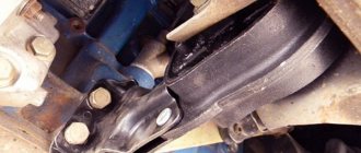
Vacuum regulator
The vacuum regulator is attached to the distributor body. Its role is to adjust the ignition angle depending on the load on the power plant. The design of the device consists of a reservoir, a membrane with a rod located in it, as well as a hose through which the regulator is connected to the primary chamber of the carburetor.
The vacuum regulator adjusts the ignition angle depending on the engine load
When a vacuum appears in the carburetor, it is transmitted through a hose to the reservoir of our device. A vacuum is created there. When this happens, the membrane moves the rod, and it acts on the rotating breaker plate, turning it counterclockwise, increasing the ignition timing.
The chopper plate rotates under the influence of vacuum created in the carburetor
Contact type distributor malfunctions and their symptoms
Taking into account the fact that the distributor is a rather complex device, it is subject to the influence of a number of negative factors that can damage the elements of its design. That is why the distributor can have a lot of malfunctions. Well, as for common device breakdowns, they include:
- electrical breakdown of the lid;
- wear of the central electrode or side contacts of the cover;
- burning of the slider contacts;
- electrical breakdown of the capacitor;
- violation of the gap between the contacts of the breaker;
- wear of the moving plate bearing.
If the contacts are severely worn, the cover must be replaced
Each of the listed malfunctions has its own symptoms, but in most cases they are of the same nature. If the distributor cover is punctured, its contacts or the slider contacts are worn out or burned, engine performance will deteriorate. The same thing will happen if the gap between the contacts of the breaker is broken, they become dirty or burnt. In this case, the following are most often observed:
- vibration;
- overheat;
- misfires;
- change in exhaust color;
- rare “lumbago” in the gas exhaust system;
- increase in gasoline consumption.
You can replace a faulty slider yourself
Failure of the moving plate bearing may be accompanied by a characteristic whistle or squeal coming from under the cover.
Types of faults
As a rule, if the distributor slider is in order, then the car engine starts the first time, without any problems. But when difficulties are observed with the plant, this indicates a damaged or broken rotor (provided that the problem is not elsewhere).
The most common malfunction of the distributor slider is its breakdown. It can be external or internal. Obviously, the external one is determined by noticeable signs - a black mark, the internal one must be checked by the presence of a spark (details below).
The breakdown occurs due to metallization of the channel. For preventive purposes, metallization should be checked regularly. This is done using a multimeter or other similar device. The channel is checked for moment of resistance. The probes of the device are connected to the place of the slider where there is doubt about breakdown.
You should know that the spark can escape either completely or partially through the formed channel.
Distributor
The sequence of work that must be performed in order to install a set of new parts on a VAZ 2107 does not make much difference.
Therefore, we can start by replacing the distributor. Remove the distributor cover to access the slider. To simplify the task of further adjusting the BSZ, you should immediately perform some preparatory measures: installing the distributor slider in a position that will be easy to repeat when installing a new distributor; mark on the block opposite the middle mark on the distributor scale, which is used to adjust the ignition. Using a 13mm wrench, completely unscrew the nut securing the distributor and then remove it. Disconnect the high voltage wire connecting the ignition coil and the distributor. We install a new non-contact sensor distributor, and you need to set the slider so that it matches the position of the old one. The body of the new distributor needs to be aligned according to the marks, the middle one opposite the one previously left on the engine body. We put on the distributor cover and a set of high voltage wires.
https://youtube.com/watch?v=%250A
Checking the ignition coil
For this purpose, it is necessary to remove the central wire from the breaker-distributor, bring it to the motor housing and turn it with the starter, and a running spark should appear. After this, we check the energy supply to a separate spark plug, for which we unscrew the working spark plug, bring its contact to ground and attempt to start the engine. In this case, the spark should come from the wire to ground. If it is absent, the reason will be a malfunction of such a system element as the VAZ 2106 ignition coil, which plays an important role in the operation of the vehicle.
During the inspection, it is necessary to observe safety precautions and work in protective dielectric rubber gloves. The “six” uses both an ignition system using contacts and a system without using distributor contacts with equal success; accordingly, a different VAZ 2106 coil is used, depending on the type of ignition system.
These types of ignition are checked using almost the same parameters. In this case, we test the system with a multimeter. It must be remembered that in the connection circuit of the VAZ 2106 ignition coil, the voltage in sections of the circuit reaches from 24 thousand to 40 thousand volts. With a small current in the system, this is not life-threatening, but an electric shock can be very sensitive.
Important: To be on the safe side, it is advisable to keep an additional ignition coil and distributor capacitor in the car. These elements of the system quite often cause the system to fail, and such products cannot be repaired
If these components are defective, it is not possible to start the engine, but replacing them is not difficult. As a last resort, in the absence of standard products, you can temporarily install analogues from other VAZ models.
Ignition system VAZ 2105
The VAZ 2105, like other classic Zhiguli models, is equipped with a contact ignition system that requires periodic adjustment. This is due to the design features of such a system. The performance of the power unit, power and fuel consumption, directly depend on the correct setting of the ignition timing. It is worth taking a closer look at the adjustments and malfunctions of this system.
What does it consist of?
The main elements of the ignition system of the VAZ “five”, which are responsible for the formation and ignition of a spark, are:
- generator;
- ignition switch;
- distributor;
- spark plug;
- ignition coil;
- high voltage wires;
- accumulator battery.
Diagram of the VAZ 2105 ignition system: 1 - generator;
2 — ignition switch; 3 — ignition distributor; 4 — breaker cam; 5 — spark plugs; 6 — ignition coil; 7 - battery; 8 - high-voltage wires Failure of any of the listed devices leads to malfunctions in the operation of the power plant.
Why is adjustment needed?
Operating a vehicle with an incorrectly adjusted ignition is a problem, as evidenced by the following symptoms:
- floods the spark plugs, which causes the engine to trip;
- power decreases;
- dynamics are lost;
- fuel consumption increases;
- The engine gets very hot;
- At idle, the engine is unstable, etc.
The listed signs indicate that the ignition timing is set incorrectly and needs to be adjusted. However, these symptoms may also indicate problems with other elements of the ignition system. Therefore, in each individual case, a more detailed study of the problem that has arisen is required.