The tachometer does not work on the VAZ 2112
During the production of the VAZ-2112 passenger car (1999-2008), it was equipped with five models of electronically controlled engines, and there were only two instrument clusters.
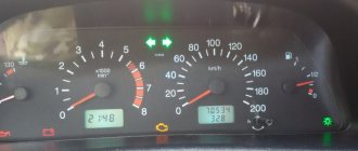
One of them was installed on the front panel, the old model, and the second, on the front panel of the new model. In appearance, they differed in the location of the instruments. On the old combination, when looking from left to right, the first instrument was the temperature indicator, and the second was the tachometer. On the new combination, the tachometer is in the extreme left position. The duties of the tachometer include providing the driver with readings of the engine crankshaft speed. The movement of the pointer along the tachometer scale is ensured by a stepper motor due to the rotation of the armature shaft on which the pointer is attached. The angle of rotation of the arrow will depend on the frequency with which the voltage pulses occur in the ignition system. Indeed, on all VAZ-2112 engines, during one revolution of the crankshaft, the spark on the spark plugs jumps twice, which corresponds to two pulses in the ignition system circuit.
But the stepper motor will not work from these pulses, so the wire from the ignition module goes to the ECM controller (electronic engine management system), where it is converted, and then through another pin the control signal is sent through the wire to the tachometer. In addition to this wire, the + from the ignition switch comes to the tachometer and one of the wires goes to ground.
If a malfunction occurs that leads to a failure of the tachometer, you will have to look for it in the three devices mentioned above: the ignition system, the ECM controller, the instrument cluster, as well as in the wires and plug connectors that form the electrical circuit for the tachometer. But, not a single device, including the tachometer, from the combination is supplied as spare parts, and in case of failure you will not be able to purchase it. This means that the entire instrument cluster will have to be changed, since it cannot be repaired.
Rarely, but there are still cases of oxidation of the contacts in the connector blocks of the instrument cluster, which is why the tachometer refuses to work. Any driver can check the condition of the plugs if desired. You just need to know in which block the required plug numbers are located. On old front panels of a VAZ-2112 car, you will have to disconnect the white block X1 of the instrument cluster and check plugs No. 1 (ground), No. 2 (low-voltage tachometer input), No. 3 (high-voltage tachometer input). And on the new front panels, disconnect block X and check plug No. 30.
troubleshooting and repair of the VAZ 2110 instrument panel | VAZ 2111 | VAZ 2112
Coolant temperature gauge
When the gauge needle is constantly at the beginning of the scale, with the ignition on, disconnect the wire from the temperature gauge sensor and connect the tip of the wire to ground. If the arrow deviates, then, consequently, the temperature sensor of the VAZ 2110, VAZ 2111, VAZ 2112 is faulty and must be replaced. If the arrow does not deviate, remove the dashboard of the VAZ 2110, VAZ 2111, VAZ 2112 and, without disconnecting the wires from the panel, turn on the ignition and connect to ground the left terminal of the temperature indicator, which is connected to plug 5 (see Fig. 7-49 ) white block (X1). The deviation of the arrow in this case will indicate the serviceability of the device and damage to the wire connecting the sensor and the pointer. When the pointer needle is constantly in the red zone, with the ignition on, disconnect the wire from the temperature sensor of the VAZ 2110, VAZ 2111, VAZ 2112. If the arrow returns to the beginning of the scale, then the sensor is faulty. If the arrow remains in the red zone, then either the wire has a short to ground or the device is damaged. The serviceability of the device can be checked by disconnecting the white block (X1) of wires from the vehicle instrument cluster and connecting plug 1 to ground and connector 10 of the white block of the instrument cluster VAZ 2110, - 2111, - 2112 to the plus terminal of the battery. In this case For a working device, when the ignition is turned on, the arrow should be at the beginning of the scale.
rice.
7-49. Connection diagram for the instrument panel of VAZ 2110, VAZ 2111, VAZ 2112 (view from the back): 1 - fuel reserve warning lamp; 2 — instrument cluster lighting lamps; 3 — right turn indicator lamp; 4 — left turn indicator lamp; 5 - backup warning lamp; 6 — coolant temperature indicator; 7 — indicator lamp for external lighting; 8 — control lamp for the carburetor air damper; 9 — oil pressure warning lamp; 10 — parking brake warning lamp; 11 — battery charge indicator lamp; 12 — tachometer; 13 — control lamp “CHECK ENGINE”; 14 — speedometer; 15 — brake fluid level warning lamp; 16—hazard warning lamp; 17 — control lamp for high beam headlights; 18 — fuel level indicator. Plugs 2, 3, 8, 9 in block X2 are the speedometer terminals 14 Fuel level indicator VAZ 2110, VAZ 2111, VAZ 2112
The checking procedure is similar to that described above. When the pointer needle of a VAZ 2110 - 2112 is constantly at the beginning of the scale and does not deviate after the tip of the pink wire disconnected from the fuel level sensor of the VAZ 2110, VAZ 2111, VAZ 2112 is shorted to ground, then it is necessary to check the device. To do this, remove the instrument cluster of the VAZ 2110, VAZ 2111, VAZ 2112 and, without disconnecting the wires from it, turn on the ignition and connect to ground the right terminal of the indicator, which is connected to plug 10 of the red block (X2) of the wires. If the device is working properly, the needle should deflect to the end of the scale. If the arrow of the fuel level indicator is constantly against o, then the serviceability of the device can be checked by disconnecting the red (X2) wire block from the dashboard of the VAZ 2110, VAZ 2111, VAZ 2112. In this case, with a working device, when the ignition is turned on, the arrow should be against the o.
Checking instruments
Coolant temperature gauge for VAZ 2110, VAZ 2111, VAZ 2112 cars.
The device operates in conjunction with a coolant temperature sensor for VAZ 2110, VAZ 2111, VAZ 2112, installed in the cylinder head.
With a temperature sensor resistance of VAZ 2110 - 2112 640-1320 Ohms, the needle should be at the beginning of the scale, with a resistance of 77-89 Ohms - at the beginning of the red section, and with a temperature sensor resistance of 40-50 Ohms - it should deviate to the end of the red section of the scale. Fuel level indicator for VAZ 2110, VAZ 2111, VAZ 2112 cars.
The device is used in conjunction with a VAZ 2110 - 2112 fuel level sensor installed in the fuel tank.
If the resistance of the fuel level sensor VAZ 2110, - 2111, - 2112 is 285-335 Ohms, the needle should be at the beginning of the scale, if the resistance of the fuel level sensor is 100-135 Ohms - in the middle of the scale, and if the sensor resistance is 7-25 Ohms - it should deviate in end of the scale. Tachometer for cars of the VAZ 2110 family.
The principle of operation of the tachometer VAZ 2110, VAZ 2111, VAZ 2112 is based on measuring the frequency of voltage pulses in the primary circuit of the ignition system.
The tachometer is checked on a stand that simulates the ignition system of cars of the VAZ 2110 family. Having connected the tachometer to the stand circuit, just like on a car, set the voltage in the primary circuit to 14V and the gap in the stand spark gap to 7 mm. Rotate the ignition sensor-distributor roller at such a rotation speed that the tachometer needle of the VAZ 2110 - 2112 stops at the main scale divisions. At this moment, check that the deviation of the rotation speed of the distributor shaft from the nominal value is within the range from -125 to +35 min. Speedometer for cars of the VAZ 2110 family
. Electronic speedometer. The principle of operation is based on measuring the pulse frequency from the speed sensor of the VAZ 2110, VAZ 2111, VAZ 2112. Check the speedometer of the VAZ 2110, VAZ 2111, VAZ 2112 by comparing its readings with a reference device. The speedometer error at (20±5)°C and a supply voltage of 13.5-14V should be (in km/h) no more than +6 and -1 at levels up to 60 km/h. At around 100 km/h the error should be no more than +8.5 and -1. At around 140 km/h no more than +11.5 and -1.
The tachometer does not work on the VAZ 2110 injector reasons
REASONS FOR A NON-WORKING TACHOMETER
The tachometer in a car is used to indicate the number of revolutions of the engine crankshaft. Let's look at why the tachometer doesn't work and how to find and eliminate the cause of the breakdown. We will definitely dwell on the device and principle of operation, which will help to find out why the tachometer stopped working, the needle twitches or behaves inappropriately.
CLASSIFICATION BY OPERATING PRINCIPLE
- Mechanical or electromechanical tachometers with direct drive. The revolutions are transmitted to the dial indicator through a flexible shaft, which, through a worm gear, receives rotation directly from the crankshaft or one of the transmission shafts. The operating principle of the indicator is based on the phenomenon of eddy current induction. The operation and design of a magnetic tachometer are extremely similar to the operating principle of a car speedometer. In modern cars, a similar tachometer design is not used.
- Electric machine. A distinctive feature is the connection to a generator. It is used primarily on diesel engines, but for the purpose of unification, a device of this type can also be used on gasoline engines.
- Electronic. The signal can be taken either from the ignition system or directly from the computer. Installed on gasoline and diesel internal combustion engines.
DEVICE AND PRINCIPLE OF OPERATION
Main components of electric machine and electronic tachometers:
- measuring unit, or signal converter. It can be based on elements of analog circuitry or built using special microcircuits;
- display unit with analogue or digital display of the number of revolutions;
- auxiliary elements.
The operation of electronic tachometers is based on the conversion of individual signals or pulses captured from the computer, ignition system or generator into a signal “understandable” for the display unit.
CONNECTION DIAGRAM
When looking for the reason why the tachometer does not work, it is first of all important to understand the connection diagram and the type of signal. There are 3 typical connection schemes:
- to a contactless ignition system (the tachometer wire is connected to the primary circuit of the ignition coil). The operating principle is based on measuring the frequency of voltage surges in the primary circuit of the ignition system. Calculating the ignition angle is impossible without focusing on the number of crankshaft revolutions, therefore the sparking frequency directly depends on the crankshaft rotation speed. On 4-cylinder internal combustion engines, a full revolution of the crankshaft corresponds to 2 voltage pulses in the primary circuit. Accordingly, the higher the crankshaft rotation speed, the greater the frequency of voltage surges;
- connection to the contact ignition system. The operating principle and connection diagram are similar to the BSZ, but the design of the measuring unit will differ depending on the voltage of the input circuit;
- connection to the engine ECU. The principle of operation is still based on recording voltage pulses in the primary circuit of the ignition system, but the signal to the tachometer comes from the engine control unit;
- connection to the generator (the tachometer signal contact is connected to terminal W of the generator). The rotation of the generator pulley is carried out by a belt drive from the crankshaft, so the rotation speed of the generator rotor will always be proportional to the crankshaft speed. The change in the number of revolutions of the crankshaft can be calculated by constantly measuring the amount of EMF generated on the winding. By its operating principle, an electric machine tachometer resembles a conventional voltmeter.
Connection diagram for tachometer VAZ-2108 and 2109
Let us immediately note that the fuel supply system – injector or carburetor – does not play a special role here. As you know, currently the most common are cars with the following engine types: gasoline or diesel. Depending on this, the tachometer is selected, unless, of course, it comes in the stock version. The thing is that on gasoline engines the tachometer reads data from the ignition coil, or rather, the impulses that arise here. However, the design of diesel power plants does not provide for this unit. Accordingly, here the tachometer reads pulses not from the ignition coil (for lack of one), but from the generator.
The first two wires (12-volt and Signal) are to contacts “B” and “K” of the ignition coil, respectively. All that remains is to secure the mass in any convenient place.
Classification by operating principle
- Mechanical or electromechanical tachometers with direct drive. The revolutions are transmitted to the dial indicator through a flexible shaft, which, through a worm gear, receives rotation directly from the crankshaft or one of the transmission shafts. The operating principle of the indicator is based on the phenomenon of eddy current induction. The operation and design of a magnetic tachometer are extremely similar to the operating principle of a car speedometer. In modern cars, a similar tachometer design is not used.
- Electric machine. A distinctive feature is the connection to a generator. It is used primarily on diesel engines, but for the purpose of unification, a device of this type can also be used on gasoline engines.
- Electronic. The signal can be taken either from the ignition system or directly from the computer. Installed on gasoline and diesel internal combustion engines.
Design and principle of operation
Main components of electric machine and electronic tachometers:
- measuring unit, or signal converter. It can be based on elements of analog circuitry or built using special microcircuits;
- display unit with analogue or digital display of the number of revolutions;
- auxiliary elements.
The operation of electronic tachometers is based on the conversion of individual signals or pulses captured from the computer, ignition system or generator into a signal “understandable” for the display unit.
Connection diagram
When looking for the reason why the tachometer does not work, it is first of all important to understand the connection diagram and the type of signal. There are 3 typical connection schemes:
- to a contactless ignition system (the tachometer wire is connected to the primary circuit of the ignition coil). The operating principle is based on measuring the frequency of voltage surges in the primary circuit of the ignition system. Calculating the ignition angle is impossible without focusing on the number of crankshaft revolutions, therefore the sparking frequency directly depends on the crankshaft rotation speed. On 4-cylinder internal combustion engines, a full revolution of the crankshaft corresponds to 2 voltage pulses in the primary circuit. Accordingly, the higher the crankshaft rotation speed, the greater the frequency of voltage surges;
- connection to the contact ignition system. The operating principle and connection diagram are similar to the BSZ, but the design of the measuring unit will differ depending on the voltage of the input circuit;
- connection to the engine ECU. The principle of operation is still based on recording voltage pulses in the primary circuit of the ignition system, but the signal to the tachometer comes from the engine control unit;
- connection to the generator (the tachometer signal contact is connected to terminal W of the generator). The rotation of the generator pulley is carried out by a belt drive from the crankshaft, so the rotation speed of the generator rotor will always be proportional to the crankshaft speed. The change in the number of revolutions of the crankshaft can be calculated by constantly measuring the amount of EMF generated on the winding. According to its principle of operation, an electric machine tachometer resembles a regular one class=”aligncenter” width=”448″ height=”412″[/img]
Typical faults
If the mechanical tachometer on a car stops working, there is mechanical damage to any of the structural elements. A broken cable of a flexible shaft, wear of the worm gear elements, the appearance of backlashes, deformations - all these reasons can cause the engine speed indicator to fail.
What to pay attention to if the electronic tachometer does not work:
- integrity of electrical wiring. In this case, it is important to check not only the signal wire, but also the ground and power supply of the instrument panel;
- quality of contacts. The presence of oxides and loose contact inside the chips may well cause the tachometer to fail;
- the integrity of the elements of the measuring unit, which are located behind the protective glass inside the dashboard. Among mechanical damage to transistors, burnout of microcircuits, tracks or swelling of resistors, the most common reason for a non-working tachometer is a violation of solder integrity. For example, on the Mitsubishi Padjero II, the appearance of microcracks in the soldering areas of the tachometer elements is a generally recognized disease.
On vehicles with an alternator connection, a non-functioning tachometer may indicate a faulty alternator. In this case, the breakdown is accompanied by the lighting of the low battery charge indicator and the sporadic lighting of a “garland” of warning lights on the dashboard.
Broken wiring
Like all electrical devices in the “four”, the tachometer has its own connection diagram. Failure to operate one of the design components leads to the problem of device failure. Broken wiring is an unpleasant problem, because... determined only with the help of special tools. To accurately determine the location of the malfunction, you need to “ring” all contacts and wiring to the tachometer. To do this, you will need a diagram of its connection.
Having experience in wiring restoration will allow you to cope with troubleshooting without a diagram. If there are no visible break points in the wiring, it is recommended to contact an electrician. The tachometer wiring in the injection versions of the “four” includes wires for power supply, ECU and DPKV. If even after repairing the wiring the tachometer on the VAZ 2114 (injector) does not work, you can remove the protective glass and check the mechanical integrity of the instrument pointer. In rare cases, the arrow may jam or break off. If the tachometer needle does not work, you should replace it together with all its components.
BEHIND THE STEEL
As practice shows, failure of the speedometer and tachometer is a fairly common occurrence.
On the one hand, such breakdowns do not affect the basic functions of the car, but on the other hand, the driver does not receive important information, which can lead to more serious malfunctions or even an accident.
Therefore, if your speedometer stops working or the tachometer needle begins to “take on a life of its own,” you need to urgently take some action.
In this article we will look at what and how to do.
General faults
During operation, have you noticed that the needle in the car’s speedometer is inactive (at any speed)?
The first thing to do is to check the tightness of the fastening nut of the speedometer tips, as well as its drive.
If, after checking, no comments are found or the work performed does not bring the desired effect, then there is a risk of damage to the speed indicator drive or breakage of the flexible shaft.
In the latter case, the part will have to be changed. At the same time, do not forget to apply high-quality lubricant to the area near the seal (Litol-24 may be suitable for these purposes).
Once the work is done, thread the shaft through the seal - this will help distribute the lubricant over the surface of the cable.
The appearance of a knocking sound while driving may indicate a malfunction of the speedometer flexible shaft.
The reasons for this phenomenon include large bends in the cable under the instrument panel, dents, and so on. Make sure that the radii of the roundings do not exceed 10 centimeters.
Sometimes while driving you may notice a “growling” sound, approximately in the front of the car. The reason may be the speedometer cable, which often makes noise in the absence of proper lubrication.
This is one of the most important car devices. Its task is to show the number of revolutions of the engine crankshaft at a certain point in time.
A tachometer breakdown is not so critical. But in the long term, it is precisely this that can cause engine malfunction and new costs for the car owner.
So how to deal with a breakdown, and what could be the main causes of the malfunction?
In fact, there are not many of them. In the case of an electronic tachometer, the LED screen of the device most often fails. Repairs in this case are problematic - it is better to replace the display.
Nissan Qashqai tachometer contacts.
Malfunctions of the tachometer are often caused by poor contact quality or faulty wiring (in this case, impulses from the engine to the device may not arrive at all).
To eliminate such troubles, you need to carefully inspect all wires for cracks and breaks. If you find a crack, simply solder it, and if a break is detected, replace part of the wiring.
The cause of a tachometer malfunction may be a failure of the engine speed sensor.
It is not difficult to diagnose the problem - the tachometer needle begins to “jump” in different directions. There is only one way to return the tachometer to “life” - by replacing this element.
Please note that the above malfunctions and methods for eliminating them are of a general nature. Each car model may have its own nuances, and we will talk about some of them in more detail.
Malfunctions on VAZ
The speedometer on the VAZ stopped working.
Most domestic autospeedometers and odometers are mechanical. So, when a mechanical odometer fails, the main reason (almost always) is a broken cable.
This problem can be easily diagnosed by a characteristic noise in the front of the dashboard.
After breaking, the steel wires begin to touch the inside of the shell and “ring.” The main reason for the break is the large radius of curvature during cable installation.
A mechanical speedometer malfunction can manifest itself in different ways. For example, the needle on the device often lies as a “dead weight” or, conversely, shows deliberately false information.
In such a situation, you need to make sure that the speed sensor is working and that there is voltage on it. Also inspect the terminals for moisture penetration.
If there is voltage at the sensor, then the problem must be looked for in the device itself. In such a situation, it is easiest to replace it.
It happens that a sensor malfunction is associated with some kind of mechanical damage. In this case, you can try to disassemble the drive and fix the problem yourself.
If there is no voltage on the sensor, it is necessary to check all electrical connections on the way to the device - wires, blocks, terminals. It is likely that the contacts are broken or oxidized.
New cars have electronic speedometers and odometers, which receive data from the speed sensor at the gearbox.
Consequently, there can be two breakdowns - either in the odometer itself (in this case it is necessary to change the entire dashboard).
Or in the sensor (we talked about it above).
VAZ tachometer malfunctions.
In the VAZ tachometer, the causes of the malfunction may differ, depending on the type of engine.
On a carburetor car there are three wires from the tachometer.
One wire is connected to the “K” terminal of the ignition coil, and the other two supply power (respectively, “plus” and “minus”).
To find out the cause of the breakdown, you need to disconnect the terminals going to the tachometer and connect the latter directly to the battery (terminal “K” remains in place).
Now you can try to start the engine. If the tachometer does not come to life, then the problem is in the device itself or in the ignition. If the engine speed indicator works normally, then the fault must be looked for in the wiring.
VAZ tachometer connection diagram
A pulse must be generated for each short circuit of pin 2 to the common wire.
From the shaper, triggering pulses of an already defined size and shape B are supplied to the input of a waiting multivibrator assembled on transistors V2 and V4. The second step is connecting the tachometer to the diesel generator. If there are no problems, then the arrow will be at zero.
It is recommended to repair the tachometer exclusively at a car service center or service stations.
On the scale, zones of dangerous crankshaft speed are highlighted with colored lines.
Malfunctions on Priora
If the speedometer on a Priora stops working, the first thing you need to do is temporarily remove the terminals from the battery.
Did not help? – Then look for a fault in the device circuit. First, check the integrity of the instrument panel fuse.
If it burns out, replace it (but first make sure that all contact connections are intact).
If the problem persists or the fuse is normal, check all the wires on the path from the speed sensor to the instrument panel. This can be done using a multimeter.
If there are no complaints about the wiring, check the motion sensor with a special scanner. If there are malfunctions, the element must be replaced.
The serviceability of the motion sensor can be determined by the behavior of the odometer. If the speedometer does not work, but the odometer counts kilometers, then the sensor is working, and the breakdown must be looked for elsewhere.
For example, problems may be in the soldering on the dashboard circuit board or, even worse, in the gearbox. But this can only be found out at a service station with the help of a qualified technician.
As for the tachometer on the Priora, there are three causes of malfunctions:
- violation of the tachometer supply circuit. In this case, you need to carefully crimp all the tips and replace damaged wires (if any);
- violation of the functionality of the controller (the signal does not reach the tachometer). Only replacing the device will help here;
- failure of the tachometer itself. This option is the most expensive, because it is not possible to change the device separately - you need to buy a new panel.
Malfunctions on Nexia
Problems with the speedometer.
Has the speedometer stopped working on the Daewoo Nexia? The first thing you need to do is check the engine index (depending on the year of manufacture, it can be of four types).
This parameter is very important, because each of them has its own speedometer features. For example, in engines with index F16D3 and A15SMS, information to the speed indicator comes from a sensor, and with index A15MF and G15MF - through a conventional cable drive.
For cable-driven speedometers, the main problem is the breakage of the cable ends (over time, their edges simply wear off and stop working normally). To determine the problem, you need to remove the instrument panel and unscrew the nut that secures the cable.
If everything is fine with the tip, pick up the cable and try to ride a little. If there is no rotation in your hand, you need to climb under the hood and twist the nut that secures the cable to the gearbox.
Here, faults such as a poorly tightened nut, cut teeth on the gears of the gearbox, or a damaged cable tip can “pop up”.
For F16D3 and A15SMS engines, where there is an electronic speedometer, the main fault may be the speed sensor.
Popular reasons are moisture ingress or failure of the unit itself. To check the sensor, you can try to remove it and twist the shaft with a drill or screwdriver. If the speedometer works normally, then the reason is in the plastic gears of the gearbox.
The tachometer does not work.
The most common malfunction of the tachometer on Nexia is breakdown of high-voltage wires.
Often, a malfunction with a twitching arrow on the device disappears after the first pull of the wire between the distributor and the ignition coil.
Such a malfunction can be diagnosed in the dark, when sparks are clearly visible.
If everything is fine with the coil and wires, but the tachometer still refuses to work, look for a problem in the switch or the wires leading from it to the tachometer.
Why does the VAZ tachometer jump?
It often happens that the needle starts to twitch. If the car is fuel-injected, then troubleshooting involves connecting a diagnostic scanner and checking the engine systems. Jumps in the TX-193 needle in most cases are also a symptom of malfunctions associated with its electrical circuit. The reasons for this behavior of the device may be:
- lack of good contact at the negative terminal of the battery;
- oxidation or burning of the brown wire on the ignition coil;
- burning or wear of the contacts of the ignition distributor cap or slider;
- wear of the distributor shaft bearing;
- shorting the red wire powering the device to vehicle ground;
- malfunction of the crankshaft position sensor (for injection engines).
A similar problem is solved by stripping the contacts, replacing the ignition distributor cap, slider, support bearing, restoring the integrity of the insulation of the device’s supply wire, and replacing the crankshaft sensor.
Another jump may be due to the inoperability of the capacitor located at the bottom of the breaker. The capacitor may be broken or its contact is very weak.