09/16/2021 17,060 VAZ 2109
Author: Ivan Baranov
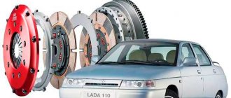
Many car owners, especially domestically produced vehicles and used foreign cars, try to carry out most of the repair work on their own. Very often, for one reason or another, it becomes necessary to remove the crankshaft pulley of a VAZ 2109 - an injector is installed or a carburetor is installed.
There are a lot of recommendations on the Internet, after reading which you might think that everything is very simple. But one problem arises, namely removing the bolt, which is not only difficult to get to, but sometimes simply impossible to move, let alone unscrew. It's also unclear how to secure the crankshaft to keep it in place. The crankshaft pulley on the VAZ 2109 is deliberately very tightly tightened and, unscrewing it, there is a possibility of damaging various components and systems in the power unit compartment or the paint.
The difficulty is that the bolt that secures the crankshaft pulley (or nut, depending on the modification) is tightened with decent force during assembly. This was done to prevent it from spinning up while moving, otherwise the consequences could be simply catastrophic.
[Hide]
Purpose
The pulley is designed to transmit torque to additional units. For this purpose, these same units have a counter pulley. It is attached to the crankshaft using a keyed connection, and fixation is carried out with a nut or bolt.
The pulley is a flat wheel with a special channel into which a rubber belt is installed. When the belt is tensioned sufficiently, it engages tightly with the pulley, and due to this, the belt drive works and transmits rotation. These elements for modern cars are made mainly from steel, aluminum, and less often from cast iron.
How to unscrew a pulley bolt in front-wheel drive models
The bolt is used as a fastening element for the crankshaft pulley in front-wheel drive vehicles. In such models, the block is placed perpendicular to the axis of the car. Unlike dismantling the nut in rear-wheel drive modifications, this method requires more time due to the need to remove additional parts. To perform the work you need to prepare the following tools:
- A jack and an additional supporting element, a stump will do just fine.
- Standard set of automotive tools.
- A socket head, the size of which is selected in accordance with the dimensions of the bolt.
- You will also need an extension arm to make work easier.
Unscrew the pulley bolt
The bolt is used primarily in the design of front-wheel drive vehicles. In this case, the block is located perpendicular to the axis. The process of unscrewing the bolt is a little more difficult because it is more difficult to get to. To perform this operation you need:
- jack, as well as a supporting element (stump or sawhorses);
- set of tools;
- socket head (depending on the size of the bolt head installed on the pulley of your car);
- the lever will fit the same as in the case of rear-wheel drive cars.
Now let's move on to the process of unscrewing the bolt, the order of our actions will be as follows:
- We lift the front part of the car with a jack and install it on a “goat” (stump).
- Remove the front right wheel.
- We open the hood and remove all the parts that prevent us from getting to the crankshaft pulley, namely the casing and the air filter. You can also eliminate other parts that may prevent you from removing the pulley.
- Remove the generator belt.
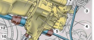
- We remove the clutch block plug and insert a pry bar into the hole to jam the flywheel teeth.
- Using the lever, we try to unscrew the crankshaft pulley bolt with a wrench. If you lubricate it with WD-40 before doing this, the process should go easier. In the case where it is not possible to unscrew it manually, you can try to perform the steps with briefly turning on the ignition, which we wrote about above.
Engine assembly
Assemble the engine as follows.
Place a clean cylinder block on the stand and screw the missing studs into it. Install the generator mounting bracket and secure it with two bolts.
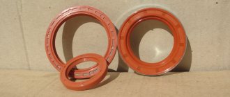
Lubricate the bearing shells and thrust half rings of the crankshaft, as well as the pistons and oil seals with engine oil. When assembling the engine after repair, install new crankshaft oil seals.
| Rice. 2.21. Installing the crankshaft thrust half-rings into the middle main bearing housings |
Install liners with a groove in the 1st, 2nd, 4th and 5th seats of the cylinder block, and liners without a groove in the 3rd seat of the cylinder block and in the main bearing caps. Place the crankshaft in the main bearings and insert the thrust half rings () into the seat of the middle main bearing.
| WARNING The half rings must have their grooves facing the thrust surfaces of the crankshaft (an anti-friction layer is applied to the surface of the half ring on the side of the grooves). A cermet half-ring (yellow) is placed on the rear side of the middle support of the crankshaft, and an aluminum-steel half-ring is placed on the front side. |
| Rice. 2.22. Marks on the main bearing caps. The caps are counted from the drive side of the camshaft |
Install the main bearing caps in accordance with the marks on their outer surface (). Unfold the covers so that the marks on each of them are on the side where the generator is installed. Tighten the cover bolts.
| Rice. 2.23. Checking the axial free play of the crankshaft |
Check the axial free play of the crankshaft. To do this, turn the cylinder block with its back side up and install a stand with an indicator on it so that the indicator leg rests against the crankshaft flange. Moving the shaft up and down (for example, with screwdrivers), measure the axial free play of the shaft () with an indicator. It should be in the range of 0.06–0.26 mm. If the stroke is greater, then bring it back to normal by replacing the old half-rings with new ones or installing half-rings of increased thickness.
| Rice. 2.24. Rear crankshaft oil seal holder. The arrows indicate projections for centering the holder relative to the crankshaft flange |
Using mandrel 67.7853.9571, press the rear crankshaft oil seal into the holder (). Place the holder with the oil seal on the mandrel 67.7853.9572 and move it from the mandrel to the crankshaft flange. Place a gasket under the holder and attach it to the cylinder block with bolts and spring washers.
| Rice. 2.20. Flywheel locking with clamp 67.7820.9526 |
Install the flywheel on the crankshaft so that the mark (cone-shaped hole) near the rim is opposite the axis of the crankpin of the fourth cylinder. Install the flywheel washer and bolts. Lock the flywheel with clamp 67.7820.9526 (see) and tighten the fastening bolts. Apply UG-6 sealant to the flywheel mounting bolts before installation. To ensure that the sealant adheres securely, degrease the bolts and threaded holes in the crankshaft before applying it.
| Rice. 2.25. Installing the piston with piston rings into the cylinder using the mounting sleeve from kit A.60604 |
Select pistons for cylinders according to class and one weight group and assemble the pistons with connecting rods, as indicated in the “Connecting rod and piston group” subsection. Using the bushing from kit A.60604, insert the pistons with connecting rods () into the cylinders.
The kit includes bushings of normal and repair sizes of pistons. Therefore, it is necessary to select a sleeve suitable for the given size of the piston being installed. You can also use the adjustable bushing 67.7854.9517.
| WARNING The pin hole on the piston is offset from the axis by 1.2 mm, so when installing the pistons into the cylinders, the arrow on the piston bottom must face towards the camshaft drive. |
Install the bearings into the connecting rods and connecting rod caps. Install the connecting rods and caps onto the crankshaft journals and tighten the connecting rod bolts. The connecting rod caps must be installed so that the cylinder number on the cap is opposite the cylinder number on the lower end of the connecting rod.
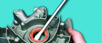
Using mandrel 67.7853.9580, press the crankshaft front oil seal into the oil pump cover. Fill the oil pump with some engine oil and rotate the drive gear several times. Install the oil pump with the crankshaft front oil seal on the mandrel 67.7853.9580 and turn the drive gear to a position so that it can be placed on the crankshaft journal. Move the pump from the mandrel to the shaft, install a gasket under the pump and attach it to the cylinder block.
| Rice. 2.26. Oil pump guide pins |
For proper installation of the pump, two guide pins () are pressed into its housing, which must fit into the corresponding holes in the cylinder block.
| Rice. 2.19. Removing the oil pump: 1 – oil pump; 2 – oil pump gasket; 3 – oil pump receiver; 4 – crankcase gasket; 5 – crankcase |
Insert the oil receiver with the O-ring into the hole in the oil pump, attach it to the oil pump and to the cover of the second main bearing of the crankshaft (see).
Install oil sump 5 with gasket 4 and secure it.
Lubricate the oil filter O-ring with engine oil and install the oil filter by hand screwing it to the fitting on the cylinder block.
| Rice. 2.27. Bushings for centering the head on the cylinder block |
| Rice. 2.28. Cylinder head bolt tightening order |
Insert two centering sleeves () into the cylinder block and install the cylinder head gasket over them. For a correctly installed gasket, the oil passage hole (edged with copper tape) should be in the area of the 5th cylinder head bolt (see bolt number).
| WARNING When reassembling the engine, always install a new cylinder head gasket. Used gaskets are not permitted. Before installing the gasket, it is necessary to remove oil from the mating surfaces of the block and cylinder head. The gasket must be clean and dry. Oil should not come into contact with the surface of the gasket. |
Rotate the crankshaft so that the pistons are in the middle of the cylinders.
Install the cylinder head, assembled in accordance with the instructions in subsection, onto the centering bushings. "Cylinder head". Tighten the cylinder head bolts in a specific sequence (). To ensure a reliable seal and avoid tightening the bolts during vehicle maintenance, tighten the cylinder head bolts in four steps:
1st step - tighten the bolts to a torque of 20 N·m (2 kgf·m);
2nd step - tighten the bolts to a torque of 69.4–85.7 N·m (7.1–8.7 kgf·m);
Step 3 - tighten the bolts 90°;
| Rice. 2.65. Cylinder head bolt |
| WARNING The cylinder head bolts may only be reused if they have been extended to a length L of no more than 135.5 mm (see ). If the bolt is longer, replace it with a new one. Before assembling the engine, lubricate the threads and bolt heads in advance by dipping them in engine oil. Then allow excess oil to drain by letting the bolts sit for at least 30 minutes. |
Step 4 - tighten all the bolts again by 90°.
Insert the coolant pump with the gasket into the cylinder block socket. Install the rear timing belt cover and attach it together with the pump cover to the cylinder block. Additionally, attach the cover with a bolt to the cylinder block and a nut to the stud on the cylinder head.
| WARNING Before installing the coolant pump, make sure that the connection between the pump pulley and the roller is secure (see subsection “Cooling System”). |
Insert segment keys into the slots at the front ends of the crankshaft and camshaft and install the toothed pulleys. Having blocked the camshaft pulley from turning, secure it with a bolt and washer.
| WARNING It is prohibited to replace the flywheel mounting bolts with the camshaft pulley mounting bolt and vice versa due to their different coating. The flywheel mounting bolts are phosphated, and the camshaft pulley mounting bolt is oxidized. |
| Rice. 2.29. Checking the alignment of the timing marks on the camshaft pulley and the rear protective cover |
Using tool 67.7811.9509, turn the camshaft until the mark on the pulley aligns with the installation lug on the rear cover of the toothed belt ().
| Rice. 2.30. Checking the alignment of the timing marks on the crankshaft pulley and the oil pump cover |
Turn the crankshaft towards a smaller rotation angle until the alignment mark on the pulley aligns with the mark on the oil pump cover (). You can turn the crankshaft using a wrench using a bolt temporarily screwed into the front end of the crankshaft.
| WARNING It is forbidden to rotate the crankshaft with the cylinder head installed, as well as the camshaft if the pistons of any of the cylinders are at i.d.t. This will cause the pistons to strike the valves and damage the valve and crank mechanisms. |
Install the tension roller with an axle (or without an axle if the roller has a plastic rim) and a spacer ring and secure it in the position of minimum belt tension.
Place the timing belt on the crankshaft pulley and, while tensioning both branches of the belt, put the left branch on the coolant pump pulley and place it behind the tension roller. Place the belt on the camshaft pulley and lightly tension it with the tension roller, turning the roller axis counterclockwise. When installing the belt, avoid sharp bends.
Rotate the crankshaft two turns in the direction of rotation and check that the alignment marks ( and ) are aligned. If the marks do not match, then loosen the belt tension, remove it from the camshaft pulley, turn the pulley to the required angle, put on the belt, slightly tension it with the tension roller, turn the crankshaft two turns again and check that the alignment marks match.
If the marks coincide, adjust the belt tension as described in subsection. "Camshaft and its drive."
Adjust the clearances in the valve mechanism as indicated in the “Cylinder Head” subsection. Install the front timing belt cover and secure it with bolts.
Carefully place the gasket into the groove of the cylinder head cover along the entire perimeter. Install the cover on the cylinder head, put the rubber bushings on the studs and attach the nuts and washers. If the bushings show signs of destruction, replace them with new ones. Tighten the nuts evenly in several steps until the washer rests on the stud. Remember that the tightness of the cover depends on the thoroughness of all installation operations.
Wrap the spark plugs and coolant temperature gauge and oil pressure warning light sensors into the cylinder head.
| Rice. 2.31. Installation of cooling system components: 1 – supply pipe of the coolant pump; 2 – thermostat; 3 – outlet pipe of the cooling jacket |
Install the outlet pipe 3 () of the cooling jacket with a gasket on the cylinder head and secure it with two nuts. Install the gasket and attach the flange of the inlet pipe 1 of the coolant pump to the cylinder block. Place the hoses leading to the thermostat onto the pipe and supply pipe, install thermostat 2 and secure the hoses with clamps.
Install the auxiliary housing with the O-ring on the cylinder head and secure it with a bolt. When installing the housing, pay special attention to the position of the sealing ring in the groove, since when tightening the nuts, it may jump out of the groove and bite between the edges of the groove and the surface of the cylinder head. If the sealing ring shows signs of being bitten, it must be replaced with a new one.
In accordance with the instructions in the “Fuel Pump” chapter, install the heat-insulating spacer with gaskets, the pusher and the fuel pump.
| Rice. 2.32. Installation of the ignition distributor sensor. The arrow indicates the mounting protrusion on the housing of the auxiliary units |
Lubricate with engine oil and place the O-ring on the flange of the ignition distributor. Attach the sensor-distributor to the body of the auxiliary units in such a position that the middle mark on the flange of the sensor-distributor is opposite the mounting lug on the body of the auxiliary units (
). At the same time, install the high voltage wire bracket under the upper fastening nut. The ignition sensor-distributor shaft is connected to the camshaft shank in only one position. Therefore, before installation, rotate the shaft so that the cams of the shaft coupling fit into the grooves of the camshaft shank.
| Rice. 2.33. Installation of the intake pipe and exhaust manifold: 1 – exhaust manifold; 2 – bracket for the supply pipe of the coolant pump; 3 – inlet pipe; 4 – warm air intake |
Place gaskets on the cylinder head studs, install exhaust manifold 1 () and tighten the central nut securing it. Then install the inlet pipe 3, warm air intake 4, bracket 2 of the coolant pump inlet pipe and secure them with nuts.
Install the crankcase exhaust ventilation hose and secure it with clamps to the pipes of the block and cylinder head cover. Install the oil level indicator.
| Rice. 2.13. Removing the generator: 1 – tension bar; 2 – generator; 3 – generator mounting bracket; 4 – generator drive belt; 5 – generator drive pulley |
Place the generator drive pulley on the crankshaft and secure it with a bolt and washer. Install tension bar 1 (see) and generator. Place the belt on the crankshaft and generator pulleys and adjust its tension as indicated in the “Generator” subsection.
Install the carburetor heat shield, spacer and carburetor. Secure it with nuts and close the top with a technological plug.
| WARNING Do not fasten (or tighten the nuts) a hot carburetor. For the tightening torque of the carburetor mounting nuts, see Appendix 1. |
Install the gasoline supply hose from the fuel pump to the carburetor and secure it with clamps. Install the hose of the vacuum regulator of the ignition sensor-distributor, as well as the hoses for supplying and discharging fluid from the cooling system to the carburetor.
Install hoses going to the heater on the outlet pipe of the cylinder head and on the inlet pipe of the coolant pump and secure them with clamps.
| Rice. 2.12. Removing the fuel pump and ignition distributor: 1 – ignition distributor; 2 – bracket for fastening high-voltage wires; 3, 5 – sealing rings; 4 – housing of auxiliary units; 6 – heat-insulating spacer; 7 – pusher; 8 – fuel pump |
Connect the high voltage wires to the ignition distributor and to the spark plugs. Secure the wire comb in bracket 2 (see).
Fill the engine with oil through the filler neck on the cylinder head cover.
How to remove a crankshaft pulley: replacing the pulley
Replacing the crankshaft pulley is a simple operation. It is enough to study the design features of your engine and prepare everything you need.
Let's look at replacing the crankshaft pulley using the example of a Renault kangoo. To perform such repairs, it is necessary to immobilize the car and place it on jacks.
- The car has a transverse engine position; to access the pulley mount, remove the left wheel;
- Since the part rotates during operation, it is necessary to fix the pulley. For this we use special clamps. In the case of Renault engines, there is a special hole in the cylinder block (closed with a bolt) into which the BMT Mot retainer is inserted. 1489 in the form of a threaded pin. It secures the crankshaft;
- To block engine rotation you need to: unscrew the bolt;
- install the fixing pin.
Replacing the crankshaft pulley
Reading time: 6 minutes.
Each car owner can independently carry out the work of dismantling and restoring the crankshaft, without additional costs for the services of a specialist. Using the recommendations will allow you to complete complex work with high quality. It is important to work carefully so as not to rip the keyway off the crankshaft.
Possible faults
Part designed to last for 10 years.
List of possible problems:
- a burst rubber layer, which causes noise when the engine is running (a sign is the characteristic hum and timing noise);
- spontaneous unscrewing by cut parts;
- worn grooves, which affect premature belt wear;
- when beating during an accident, part of the part may break off, which leads to further breakdowns (therefore, after an accident, it is important to check the technical serviceability of the AvtoVAZ);
When purchasing a functional disk separately, you must choose the original part, no matter how much it costs. This contributes to reliable and long-lasting operation of the vehicle. Even if a simple part is turned, the size may not match.
Purpose of the crankshaft pulley
The design serves as a transmission from the drive to the attachment and consists of a massive disc-shaped cast iron part that is located on the axis. In addition, it contributes to cushioning during changes in rotation, balancing of the rotating device, and cooling of belts.
The design has a gap, with the help of which the disc is mounted on the camshaft in the front part, which comes from the carburetor or from the valve injector. The fasteners will be placed on it. And on top there are holes for attaching V-belts and poly-V-belts. The structure itself is quite heavy, so during manufacturing at the factory holes are made to reduce weight.
The part comes in two types: a crankshaft damper pulley and a regular one. Unlike the damperless part, the part has massive rings. There is a gasket on the outside, which is located separately from the base. The gasket reduces vibrations. In addition, the part is equipped with an outer disk and periphery connected by durable rubber. The rubber gasket protects against temperature changes and other influences. With prolonged use of the vehicle, the gasket wears out. Therefore, it needs to be changed from time to time in order to keep intact the more important part - the massive disk. External aluminum car part with irregularities. The toothed coating facilitates the operation of the part position sensor.
Features of work
At first glance, there is nothing difficult in simply removing the bolt securing the pulley to the engine crankshaft flange. However, this is not quite true. The crankshaft pulley bolt very rarely unscrews and always sticks. Therefore, there is a risk of breaking it. First we need to get to this pulley. To do this, unscrew the bolt securing the generator to the tension bar. The latter is attached to the engine cylinder block.
The generator is moved towards the engine, and the drive belt is removed from the pulleys. It can be rivulet type or serrated. Now, having reached the desired element, proceed to further actions.
A little materiel
Before you twist anything, you need to know where this part is located and what functions it performs. So, in very simple words, the crankshaft pulley is a special wheel that is located outside the engine.
It is fitted with a timing belt, alternator, pump, air conditioning compressor, etc. Otherwise, the crankshaft pulley is necessary so that the engine can drive attachments and the timing mechanism.
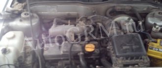
Without a pulley, the operation of the internal combustion engine and the movement of the car is impossible, since the torque from the crankshaft itself will not be transmitted to other engine components. When looking for this part under the hood of a car, you should focus on the generator. The object you are looking for will be below.
It fits onto the protruding part of the crankshaft and is held from turning by a key. It is secured with a nut (less commonly, fastening is done with a bolt). How to unscrew the crankshaft pulley bolt is the main problem.
There are several types of crankshaft pulley:
- Pulley for V-belt. This type is present in any Soviet-made car (including trucks and buses). It has an all-welded or solid-cast design with a groove that completely follows the profile of the V-belt.
- Toothed pulley. It is used on many modern engines after the timing chain has been replaced with a timing belt in order to lighten the entire structure. This belt has teeth on its inner surface. Accordingly, teeth are also made on the outer rim of the pulley.
- Damper pulley. Found on many light-duty vehicles, as well as minibuses. This pulley consists of two parts: an outer working disk and an inner race. A rubber damper pad is placed between them.
This is done in order to reduce the impulse mechanical impact experienced by the gas distribution mechanism and timing belt during engine starting and sudden changes in crankshaft speed. The side effect in this case is the relatively short life of the pulley, and also the fact that the part requires increased attention from the driver or mechanic.
After getting acquainted with the part itself, you can consider situations in which you will have to unscrew the crankshaft pulley nut or the bolt securing it.
Why is it difficult to remove the pulley?
No. 1. Depending on the engine design, make and model of the car, the difficulty of removing the pulley varies. Some machines have a lot of space to comfortably carry out repair work, while others have very little free space. The pulley design elements cover the pulley.
The structure of pulleys is also different, there are 2 types:
ordinary; damper.
Damper pulleys have an additional outer ring with an elastic band in their design, which absorbs vibrations and micro-vibrations.
Before you start removing the pulley, you need to loosen the tension nuts and bolts, remove the generator and power steering belt.
No. 2. In the factory assembly, the pulley is seated on the engine crankshaft, pressed with a bolt or nut and tightened with high compression force. Thus, the factory assembly is very strong. Therefore, if you have never removed the pulley, it will be more difficult to dismantle it the first time.
In addition to tightening with the maximum permissible force with a special torque wrench, during operation, the engine becomes very hot, the threaded connection is tightened even more and sticks. And external factors influence the outside, due to which the threaded connection may be subject to corrosion.
Some engine models cannot be repaired; they are disposable. These are, for example: 1AZ-FSE, 3UZ-FSE. Each power unit was examined in detail.
No. 3. If you disengage the clutch, the engine crankshaft can be freely turned with a wrench. Therefore, in order to unscrew the crankshaft pulley nut, you need to stop the shaft from turning. If, when you press the clutch, the speeds do not change, then it is not working. Air may have entered the system. In this case, you need to bleed the clutch.
Why are special technological holes made in pulleys? In auto repair shops, there is a special device for fixing the shaft, which must be bolted to the pulley and the shaft locked.
If there is no special device for fixing the shaft, which is screwed to the pulley, then you need to install good anti-roll devices under the wheels of the car and put 4th gear on the gearbox.
Or, the third option is to rest a pry bar against the flywheel teeth and fix the crankshaft from turning while unscrewing the pulley nut.
Another option is to insert a pin into the pulley hole, and install a pry bar around the pin and the second stop, as in this figure.
What's stopping you from removing the crankshaft pulley?
The vehicle's owner's manual and repair manual describe the procedure for removing the crankshaft, including removing the pulley, in a nice, concise manner that makes it seem easy to do. But in reality, everything turns out to be not so simple. There are several reasons for this:
- The location of the pulley in the engine compartment is inconvenient for work. It is hidden behind the generator and access to it is limited by elements of the body structure. Pulleys come in regular and damper types, which have an additional outer ring with a rubber seal to absorb vibration. To get to the pulley fastening elements, you need to loosen the tension bolts and remove the generator and power steering belts. And even after this, when performing dismantling work, special care should be taken in applying forces so as not to accidentally damage surrounding nearby parts and the paintwork of the body.
- When installed at the factory, the crankshaft pulley is clamped with a high-tension bolt or nut to ensure a secure fit. During engine operation, the right-hand mounting thread further strengthens the clamping force. High temperatures and environmental influences aggravate this process over time through oil coking and metal corrosion. As a result, the fastening nut or bolt firmly adheres to the pulley body, and it is not easy to break this bond of metals without knowledge of special methods.
- When the clutch is disengaged, the crankshaft rotates freely using any wrench. Therefore, before unscrewing the crankshaft pulley, you should resolve the issue of securely fixing its position in order to prevent rotation when unscrewing the nut. In workshops, special devices are used for this, which are bolted to the pulley into the technological holes and create a reliable stop against rotation. In the absence of such devices, this problem can be solved by installing reliable stops under the wheels and setting the 4th speed of the manual transmission. You can also fix the crankshaft flywheel by resting a pry bar against its teeth or holes.
Folk tricks
Let's look at a few folk car tricks that have helped more than one driver.
- Each threaded connection, by the way, not only on the part of the car, can be unscrewed by first lubricating it with a special oil, for example: HP, sunflower oil, vinegar, brake fluid.
- In rare cases, lightly tapping the edges of the bolt and nut with a hammer or wrench helps.
- Removing a bolt or nut does not mean removing the pulley. How to unscrew the crankshaft pulley without a special key? The pulley sits very firmly on the shaft; it can be removed using a pry bar or a screwdriver and carefully pry it off in several places.
Pulley removal
Unscrewing a fastening bolt or nut is only half the battle. Next you need to pull the pulley out of the shaft. The pulley cannot be removed easily by hand unless its seat is broken. In addition, if the pulley fits tightly onto the shaft, it is also secured against turning by a key.
There are special pullers for removing the pulley from the shaft. There are mechanical and hydraulic pullers.
The design of a mechanical puller is simple. Usually it has three legs, with which you need to hook the pulley itself, and rest the central rod against the shaft. After which, you need to rotate the rod, the legs will straighten and pull the pulley towards you. There are even simpler pullers that you can make yourself. If there is no removable device for the pulley, then you can use pry bars. If one person is filming, then take turns, moving it a little on each side so that there is no distortion. If there are two, then at the same time, from different sides, the pulley is pressed out from the crankshaft with a sharp movement.
It also happens that when using a puller, the walls of the pulley grooves cannot withstand and break off. Therefore, when using pry bars, they must be engaged as close to the shaft as possible.
Recommendations
Comments 75
Hello everyone, at idle the pulley is chattering, but at speed it evens out, what could be the problem?
I had this. As it turned out, the corrugation of the exhaust pipe of the muffler had burnt out, gases were escaping, and this caused the pulley to wobble. Even experienced craftsmen could not find the connection, but after replacing the corrugations, the vibrations went away. Check the exhaust system for leaks. Moreover, there does not have to be a hole in the muffler; I discovered gas breakthrough through the corrugation only at high speeds.
The pulley also dangles and aligns at speed at idle, or rather dangles, checked the tightening of the bolt in the service, it is tightened correctly, the question is what. What are the consequences of a loose pulley? I read on the Internet what leads to crankshaft wear? Is it so? And is it possible to drive like this or change the pulley itself since it’s crooked?
It is undesirable to drive like this, as it creates additional variable loads on the crankshaft. There can be many reasons. Maybe the pulley is crooked, maybe the engine is worn out, maybe the engine is just unstable at idle. I actually had a problem with a burnt out muffler. Start with an inspection of the exhaust system and power and ignition systems. If they are in order, then try to change the pulley or deal with the engine.
I read your comment and don’t understand at all how a leaky muffler exhaust can affect the looseness of this pulley? There is no vibration on the engine, by the way, at idle the only problem is that it doesn’t start hot with the key, but it starts with autostart, there was unstable operation, the air leak was removed from the damper manifold, the spark plugs were changed, the armored wires of the ignition coils were all. Now this is the problem.
At that time I didn’t even understand what the connection was with the muffler. But the fact is a fact, after replacing the burnt-out corrugation, the beating of the pulley stopped. I can’t explain the physics of the process, but that was exactly the point.
Great! And we, truck drivers, just set it to speed, and the handbrake also helps.
You can’t do this on a car with an automatic transmission, even if it’s a Suzuki.))
If you look at it, on cars with automatic transmission you cannot turn the wheels with the engine not running and the transmission engaged. Why can’t you turn the engine by the crankshaft pulley with the transmission connected? Although the proposed method is sensible, it’s bad that Vitarika doesn’t make holes in the flywheel.
On cars with automatic transmission there is no mechanical connection between the engine and transmission; torque is transmitted through the torque converter only when the engine is running. Therefore, with the help of an automatic transmission, the crankshaft cannot be locked, as with a manual transmission.
Replacing the timing belt on VAZ 2108, 2109, 21099 cars
The frequency of replacing the engine timing belt on VAZ 2108, 2109, 21099 vehicles is 75,000 km.
Many auto mechanics recommend replacing the timing belt a little earlier - 55-60 thousand km, since the quality of timing belts supplied as spare parts for VAZ 2108, 2109, 21099 vehicles leaves much to be desired.
In addition, every 10-15 thousand km it is necessary to inspect the condition of the belt for oiling, abrasions, breaks and cracks (see “Checking the timing belt”). We replace a defective timing belt immediately, without waiting for the mileage period. The procedure for replacing the timing belt of an engine on a VAZ 2108, 2109, 21099 is not complicated; it can be done even in camping conditions in a short period of time without special tools and devices.
Necessary tools, devices, spare parts
— Socket wrench or socket 19 mm;
— Ring wrench, open-end wrench or 17 mm socket
— Socket wrench or 10 mm socket
Reanimation of machine drying
If you have a drying-washing machine, or you want to buy one, or you just heard about such a miracle of technology, then the post should be useful to you.
Historical reference:
There is such a miracle of modern technology - a drying machine. This is when you throw a pile of wet socks into it after washing, and take out a pile of dry and soft ones. There is a 2-in-1 machine option: washing and drying. This is when you throw in a pile of smelly dirty socks and get out a pile of dry and clean ones. [joke about missing socks] It would seem that throwing things from one machine to another is just an unnecessary task and is better than a 2-in-1 machine, they also take up less space. But purely drying ones have a lot of programs for different types of fabric, humidity sensors are more accurate and all that. The question is controversial, there is no answer.
The story itself:
As the owner of an LG 2-in-1, I couldn’t be happier that I didn’t have to look for where to hang a duvet cover and a sheet at the same time. But some time ago the machine began to not dry enough, they were dreaming about dull sensors, the warranty was already out, well, it’s bad to dry - nothing, let’s run the drying a second time, maybe it will help (it didn’t always help, by the way)
And then I came across this video: (the description is below it, you don’t have to watch it, but let it be here)
Briefly, what happens: the machine becomes clogged with microparticles of fabric in a certain place and does not allow hot air to pass through for drying, as a result of which the laundry remains wet, although it has been dried for a long time. This can be treated by removing the covers, a screwdriver, a couple of neat paws and patience.
We pulled out this slide from ours, and something else flowed down the drain during flushing:
These are all scraps from fabric fibers (not threads, but tiny specks of dust), when dry they are like felt boots, when wet they fall apart very easily. And, thank Cthulhu, it doesn’t smell of anything, because it constantly undergoes heat treatment.
And, hurray, after the first launch everything worked and the clothes were dry!
Here is another detailed video about disassembling LG*, it has text in English, but with a close-up of all the screws: *Googled for myself, so I’m too lazy to look for other brands, I recommend using English and other languages to search, because the videos are not official and they are called anyhow
By the way, the bottom nasty bolt can be unscrewed through the hole on the left (with a white plastic cap) if you move the entire drum towards it, but the option with a drill is also not bad.
The moral of this story is that equipment needs to be maintained, then it will work properly. And it’s not always obvious what exactly needs to be done with it; the machine also has a filter on the bottom, like any regular one (and there’s also a lot of “dust” that collects there, but it’s easier to clean).
Dryers have a separate, large, easily removable filter, which manufacturers recommend cleaning almost every time you use it.
An additional thought: if all this accumulates in the machine, then without it all this dust would fly around the apartment, not fatally, but in fact noticeable - you spread the sheet, and it doesn’t create a nasty haze in the air.
The answer to the popular question “but the linen will all be wrinkled. “- if you take it out immediately, it won’t work, the effect is like a steam generator or even an iron. If you let it cool in the car, it’s crumpled, Christmas tree physics.
How to unscrew the crankshaft pulley yourself
One day, every car owner is faced with a problem that cannot be solved without prior preparation. One of them is removing the crankshaft pulley.
How to unscrew the crankshaft pulley
As a rule, difficulties are associated with dismantling and installing new cuffs, which become deformed and cease to perform their functions. As a result, an oil leak appears that has to be repaired. For an experienced car owner, removing the crankshaft pulley is not a problem. Another thing is for beginners who are just learning the basics of car repair.