Components of the ignition system of the VAZ 2106
Previously, a distributor of the R-125B brand was installed on the car. This unit was mounted on the machine together with a carburetor marked 2103. The distributor had a special mechanical corrector in its design, and there was no vacuum regulator. The VAZ 2106 is equipped with spark plugs of type A17DV or plugs that have similar technical characteristics.
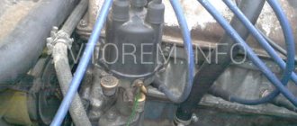
The design of the automotive system uses a VK347 type lock, equipped with an anti-theft device. The car uses a B117-A type ignition coil, which has an open magnetic circuit and is oil-filled and sealed.
The VAZ 2106 ignition is contact-based, but it is worth noting that sometimes there is also a contactless version of the system. The contact system is considered simpler in its design. VAZ contact ignition requires regular maintenance and monitoring of the condition of the contacts.
How to set the ignition on a VAZ 2106 - procedure
First, you will need to install the ignition mark. The crankshaft can be rotated either using a ratchet or using a special wrench using the nut. On the front cover of the engine and on the crankshaft pulley there are ebbs and notches, the combination of which corresponds to different ignition timing:
- The first mark in the direction of travel is an advance of the ignition angle by 10 degrees. Angle advance is an adjustment to the fuel burning rate. So, 10 degrees is the mark for 72 gasoline.
- Next comes the middle mark - 5 degrees ahead. It is for 80 gasoline.
- The last, short mark is a lead of 0 degrees. This means that the mixture will ignite exactly at the moment when the piston is at top dead center.
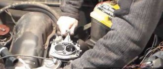
After the installation of the ignition mark is completed, you must immediately set the required gap in the contacts, naturally, where they exist. To do this, remove the distributor slider and unscrew the breaker fixing screw.
Before setting the gap, it is advisable to clean the contacts with sandpaper (600-800)
The gap between the breaker contacts in the open state should be 0.35-0.40 mm. For this you will need a flat probe.
Well, now we go directly to the ignition installation of the VAZ 2106. We unscrew the distributor mount (nut 13), and then pull it out of the housing.
Now you need to insert the distributor into place, taking into account several mandatory points:
- We set the top dead compression stroke mark in the first cylinder; accordingly, at this moment the spark should appear in it. In order to catch this moment, we put the cover on the distributor and mark the place where the armored wire from the spark plug of the first cylinder enters. Now you need to remove the cover and align the outer contact of the slider exactly opposite the mark. That is, at the moment when the piston is at top dead center, a spark is supplied from the central wire of the distributor through the contacts of the runner to the armored line from the first cylinder.
- Next, to set the ignition to 2106, you need to draw an imaginary line between the roof latches and install the distributor in place so that this line is parallel to the engine block. It’s worth saying right away that you won’t be able to get into the drive splines the first time; you’ll have to twist the housing a couple of millimeters. This is not scary, because the ignition installation requires subsequent adjustment. It is important that the distributor is completely seated in place so that it rests against the block. Next, we pull it into place.
Ignition coil and other elements
It is somewhat different in the contactless system from the one used in the classical one. The reason is the different value of the secondary voltage. Thus, when operating an internal combustion engine with a contact (including contact-transistor) ignition system, 25-30 thousand volts are required to form a spark gap. But in a non-contact system you need to generate over 30 kV, sometimes even up to 40 kV. Therefore, more turns are needed in the secondary winding.
The remaining elements are completely similar for all three designs discussed above. You choose the armored wires connecting all high-voltage circuits yourself. They can be either in a silicone or rubber shell. Contactless ignition 2107 can work with any high-voltage wires recommended by the manufacturer. Candles must be used those recommended by the manufacturer. In this case, you can again choose the brand yourself.
Device malfunctions
Replacement and repair of the distributor on the domestic “six” is carried out in the event of incorrect operation of the mechanism.
We recommend: Opel Astra H fuses and relays in a complete set
Below are the main symptoms of breakdowns that indicate possible malfunctions:
- The vehicle jerks while driving. Moreover, these jerks are completely uncharacteristic of a car.
- The engine generally does not start.
- When trying to accelerate the car, the car may also jerk, and the acceleration process itself takes a lot of time, and the engine may detonate - the piston rings knock.
- Increased fuel consumption.
As you can see, in general the symptoms are similar to those that appear when the ignition is set incorrectly. Of course, if such symptoms appear, it cannot be said for sure that the fault lies in the distributor, but attention should also be paid to diagnosing this unit.
As for the breakdowns that may force the car owner to repair or replace the mechanism, they are as follows:
- The unit slider is worn out and burnt out.
- The problem lies in the cover itself - the contacts on it could have burned out.
- Hall sensor failure. The problem may be associated not only with a breakdown of the controller, but also with poor contact on the regulator plug.
- Another reason that domestic drivers encounter quite often is the distributor bearing. After a long period of use, it could become loose, but it could also simply jam.
- Presence of mechanical damage, including cracks on the cover.
- Engine fluid gets into the distribution unit; usually the problem is related to the seal of the cap.
What benefits can you get?
But you will get many benefits if you install an electronic ignition on the VAZ-2106 instead of a contact one. It’s better to start with the fact that any driver likes to drive more than to repair the car. But frequent replacement of the contact group or its cleaning and adjustment causes terrible hostility among motorists. Moreover, the contact can fail at any time, so you need to have a spare one with you. But the electronic system on this side is much more reliable and does not require frequent maintenance.
But the most important thing happens in the engine - the very heart of any car. His work is returning to normal. It begins to function correctly, regardless of the rotation speed. Whether at idle or at 4000 rpm, the engine runs perfectly smoothly, stably, and the air-fuel mixture ignites in a timely manner. And this improves your comfort, increases engine reliability, and most importantly, increases its service life.
Distributor diagram and principle of its operation
On all VAZ cars, the distributor has the same design and operating principle. Thus, our VAZ 2107 is no exception.
The main principle of its operation is the connection between the distributor and the crankshaft or simply the crankshaft. As soon as the piston of the first cylinder reaches top dead center (or TDC for short), the contacts in the breaker open. That is why voltage appears in the coil, transmitted through the slider of the cover, which the distributor has, to the spark plug of the first cylinder. Meanwhile, combustion of the fuel-air mixture begins, and the rotation of the crankshaft “turns on” the breaker cam. It also starts to spin. The same thing happens with the other cylinder and spark plugs.
Thus, the rotation of the breaker cam, the crankshaft, their relationship with the slider, which results in a spark, clearly demonstrates the structure of the distributor on the VAZ 2107.
Removal and installation of the ignition distributor of the VAZ 2106 distributor
The ignition distributor (distributor) is removed from the VAZ 2106 car for repair or replacement. The engine of the VAZ 2106 model has a distributor of type 30.3706.
To distinguish it from distributors of other models, a mark (ring groove) is made on the shank. To remove the distributor from a VAZ 2106 car you will need: a spark plug wrench, a bit, two “7” keys, a “13” wrench, and a screwdriver. 1. Remove the tip from the spark plug of the first cylinder and unscrew it.
2. Close the spark plug hole with your finger.
3. Turn the crankshaft until the compression stroke begins in the 1st cylinder (air will begin to escape through the spark plug hole). Then, while continuing to turn the crankshaft, align mark d on the crankshaft pulley (highlighted with chalk) with the middle mark b (if you are using gasoline with an octane rating of 92 or 95) or the extended mark c (if you are using gasoline with an octane rating lower than 92). Reinstall the spark plug of cylinder 1 and connect the high-voltage wire to it.
4. Disconnect the hose from the vacuum ignition timing regulator. 5. Remove the high-voltage wires from the sockets of the distributor cover.
6. Unscrew the nut securing the distributor, remove the spring washer and plate. 7. Remove the distributor from the engine.
8. Turn over the distributor and, holding the lower nut, unscrew the nut securing the low voltage wire; remove the washer and wire. 9. Unfasten the holders and remove the cover from the new distributor.
WARNING
Before installing a new distributor on a VAZ 2106 car, check and, if necessary, adjust the gap between the contacts of the breaker.
10. Install high-voltage wires into the cover of the new distributor in accordance with the operating order of the engine cylinders.
NOTESThe operating order of the engine cylinders is: 1-3-4-2. The distributor rotor rotates clockwise. Cylinder numbers are marked on the distributor cap and on the engine cylinder head.
11. Connect the low-voltage wire to the new distributor.
12. Turn the rotor of the new distributor to a position in which its outer contact (shown by the arrow) will be directed towards the contact of the 1st cylinder on the distributor cover. NOTE
When the outer contact 2 of the rotor coincides with mark a on the cover, it simultaneously coincides with the head of screw 1 on the distributor body.
13. While holding the distributor shaft from turning, insert it into the socket on the cylinder block so...
14... so that the line passing through the spring latches is approximately parallel to the axis of the motor. 15. Secure the distributor in this position to the cylinder block without completely tightening the nut. Connect the hose to the vacuum regulator. 16. After installing the distributor on a VAZ 2106 car, check and, if necessary, adjust the ignition timing (see “Checking and adjusting the ignition timing”).
Replacing the distributor (ignition distributor) on a VAZ 2108-VAZ 21099
Direct replacement
Removal
1) First, de-energize the engine system by disconnecting the negative terminal from the battery. (Instructions and procedures are described in the article: “Replacing the battery” in the first paragraph).
2) Next, disconnect the high voltage wires from the distributor cover.
3) Remove the vacuum hose from the vacuum regulator fitting.
4) Then completely unscrew the top nut securing the distributor and wire holder.
5) Remove the holder from the car engine.
6) Use your hands or a screwdriver to disconnect the wire block from the distributor.
7) Now unscrew the two remaining nuts that secure the distributor at the bottom: use a wrench to unscrew the left nut of the distributor.
Then unscrew the right nut.
 Remove the distributor directly from the engine of the car.
Installation: 1) First, remove the two screws from the cover and remove it.
2) Then turn the slider with strictly outer contact opposite the “first cylinder” terminal located on the cover.
3) Install the distributor in the reverse order of removal.
4) Place the negative terminal on the battery and set the initial ignition timing. (We recommend that you familiarize yourself with the process in the article: “Installing the ignition”).
Changing the cover
1) First, disconnect all high-voltage wires from the cover.
2) Then use a Phillips screwdriver to remove the screws holding the plastic cover to the distributor.
3) Remove the cover and replace it with a new one.
Note! The cover on the distributor is installed in only one position. And the high voltage wires are put on the cover in the order: 1-3-4-2. There is a marking “1” on the distributor cover itself, start counting from there in order, counterclockwise.
DIY installation and connection diagram
So, having made your choice, we suggest that you familiarize yourself with the necessary tools, the replacement procedure and video instructions.
Tool
From the tool you will need:
- Key 13 - remove and install distributor
- Screwdriver - tighten the screws.
- Drill with a metal drill, diameter for self-tapping screws
- Two self-tapping screws - screw the switch.
- Keys for 10 and 8 - remove and install the coil.
How to install step by step
- Disconnect the negative battery. Before starting work on the ignition system, disconnect the negative terminal of the battery
- Remove the distributor cover with high-voltage wires. Removing the ignition distributor cover
- Disconnect the high-voltage wire on the coil. Disconnecting the wire from the ignition coil
- Using short turns of the starter, set the ignition distributor slider perpendicular to the engine. This is how the distributor should be installed relative to the engine
- Mark the position of the distributor with a marker on the engine. Installing the ignition distributor slider
- Unscrew the nut holding the distributor using a 13mm wrench. Disconnect the wire connecting the device to the coil. Before removing the ignition distributor, disconnect the wire that goes to it from the coil
- Insert the new ignition distributor into the engine by removing the cover. The ignition distributor must be inserted into the standard socket
- Turn the distributor body so that the middle mark on it coincides with the mark you previously placed on the motor.
- Tighten the nut securing the new ignition distributor. The nut holds the ignition distributor in place
- Put on the distributor cover and connect the wires to it. This is how the cover is installed on the distributor
- Replace the ignition coil with a new one. A new system requires a new coil
- Connect the original and new wires to the coil. To connect everything correctly, use the diagram. All connections must match the diagram
- Install the switch in any convenient location. Drill holes and screw screws into them to hold the device. Check the connections of all VAZ-2106 systems. The switch will not take up much space under the hood and its location does not matter
- Start the engine. If it doesn’t start the first time, you can turn the distributor a little. This will change the ignition timing.
Adjusting contact gaps VAZ 2106-2103
Has your car's fuel consumption increased, the engine starts poorly and does not idle stable, is the car clearly not developing the required power? All these signs indirectly indicate that the angle of the closed state of the contacts (UZSK) is broken. The gap between the breaker contacts is a very important parameter that needs to be monitored.
Adjustment of the ultrasonic vibrating system must be carried out using special equipment, so it is recommended in such cases to use specialized workshops. As they say at home, UZS is set in case of emergency, that is, when it is necessary to determine the cause of a malfunction or, for example, when independently setting the ignition timing. Usually the ultrasonic vibrating system is set approximately according to the gap between the contacts.
We will consider a method for adjusting the contact gap of the VAZ 2106 with our own hands, that is, we will simply set the required gap between the contacts of the breaker, so that you simply understand the principle of adjustment and you can, if something happens, navigate yourself when performing repair work to set the ignition timing.
Let's get started:
- Prepare a set of probes, we will need a probe with a thickness of 0.40mm.
- Unfasten the holders from the ignition distributor cover and remove it.
- Remove the ignition distributor rotor by unscrewing the two screws securing it.
- Using a special wrench, turn the crankshaft to such an extent that the breaker cam is in a position in which the breaker contacts are maximally open.
- Check the gap between the contacts of the breaker; if the gap is larger or smaller, then loosen the screws securing the contact stand one by one and slightly moving the stand with a screwdriver, achieve the optimal gap between the contacts of the breaker.
- Tighten the rack mounting screws and install all parts in the reverse order of removal.
At this point, the repair work to adjust the gap between the contacts of the breaker on the VAZ 2106 car has been completed.
On a note:
- Always, after adjusting the ultrasonic vibrating system, the ignition timing is off, adjust it.
- Before adjusting, pay attention: as a rule, as a result of work, a tubercle is formed on the surface of the fixed contact, which must be removed using a file. And on the moving contact, a depression is formed; you should not touch it. If the contacts are too worn out and when they are closed, they do not completely touch the planes or touch askew, then it is necessary to replace the contact board.
Contact ignition VAZ 2106
In the photo - VAZ 2106, which is an exact copy of the Fiat 124
Different ignition systems were installed on the car at different times, but the Fiat contact design is considered a classic. Its device is incredibly simple - an ignition coil, a distributor, a bundle of high-voltage wires and the right spark plugs. This is all that is needed for the correct operation of the engine. On the first batches of sixes, until 1980, a P125-B distributor of the simplest design without vacuum adjustment of the ignition timing was installed. After installing the standard Ozone carburetor, it became possible to equip the distributor with a vacuum advance angle adjustment system.
Structurally, distributors differ only in the presence of a vacuum membrane chamber, which is connected to the primary chamber of the carburetor. At a certain period, a distributor was installed without a vacuum chamber and it was structurally similar to the old one. Reel B117-a, sealed, filled with oil, with open magnetic conductors. In short, there is practically nothing to break. All that remains is to check the condition of the system elements and you can begin adjusting.
Instructions for setting the ignition of the VAZ 2106
Let's look at 3 known methods of adjusting the ignition angle on VAZ engines.
This method allows you to very accurately set the ignition to the marks, and does not require removing the distributor and valve cover. The entire adjustment process takes 5 minutes. A strobe light can be found at any auto store. The procedure is as follows:
- With the car turned off, loosen the nut securing the distributor, having first made a mark of the initial position on its body;
- On the front engine cover we find two short and one long marks, clean them of dirt and oil;
- We connect the negative wire of the strobe to the engine ground, the positive wire to the ignition coil, and a special clamp to the high-voltage wire of the first cylinder;
- We start the engine and turn on the strobe. The light from its lamp directed at the pulley will show the true position of the ignition timing;
- Slowly turning the distributor body, we achieve alignment of the mark on the crankshaft pulley and the bosses on the front cover;
- We check the engine speed using the tachometer and, if necessary, adjust the idle speed on the carburetor;
- Tighten the distributor fixing nut.
The marks have values of 00, 50 and 100 relative to top dead center (TDC). For proper operation on 92 gasoline, select an advance of 0 degrees.
If you don’t have a strobe handy and you need to set the ignition accurately, it is recommended to use a simple 12-volt car lamp. Two wires with stripped contacts are soldered to it. The settings are made in the following sequence:
- Unscrew the spark plug from the first cylinder;
- Using a ratchet or a suitable wrench, rotate the crankshaft until the compression stroke begins in the first cylinder;
- We combine the marks on the crankshaft pulley with the tides on the cover body, for 92 gasoline we select the middle or last short one;
- Remove the distributor cover, noting the position of the slider on the rotor opposite the first cylinder;
- We loosen the fastening of the distributor housing, the cover fasteners should be parallel to the engine;
- The distributor is installed immediately after its removal in this position - this simplifies further adjustment;
- We connect the wires from the light bulb to the body (minus) and the low-voltage wire inside the distributor (plus);
- Turn on the ignition in the cabin (do not crank the starter);
- If the ignition is set correctly, the contacts will be open and the light will not light up;
- You can twist the distributor body and achieve a stable position in which the light goes out;
- Tighten the distributor fastening, install the cover and turn off the ignition. The adjustment is complete.
It is possible to quickly adjust the approximate position of the distributor without any instruments. It will take a little patience and good hearing. This method is applicable only if the carburetor and timing belt are in good working order. We proceed this way:
- We start the engine, let it warm up to operating temperature, the throttle handle in the carburetor should be recessed;
- We slightly loosen the fasteners of the distributor and begin to carefully turn it;
- When turning at large angles, the engine will stall or, on the contrary, increase speed;
- It is necessary to achieve smooth idle speed in the range of 700-800 rpm without extraneous knocking and detonation;
- In this position we fix the distributor.
This adjustment by ear requires testing on the road or with a strobe light, but for initial tuning it is the best option.
Replacing the VAZ 2106 distributor with your own handsAutoRemka
Distributor malfunctions lead to malfunctions in the ignition system. You can guess that the distributor is faulty by such characteristic signs as sudden jerks of the car while driving and discordant operation of the engine at idle.
The essence of such a procedure as repairing or replacing a VAZ 2106 distributor is to replace the worn parts included in it.
To carry out repair work you will need:
2 7 mm wrenches, 10 and 13 mm wrenches, two screwdrivers, a hammer, a set of flat feeler gauges, mandrels for knocking out and pressing in distributor bushings (bearings), and tweezers.
When all the tools are prepared, you can start working.
1. We unscrew the 2 fastening screws that secure the connection of the distributor rotor with the support plate of the ignition timing regulator, after which we remove the rotor itself.
2. The springs and weights of the centrifugal ignition timing regulator must be marked so as not to get confused during assembly and put everything in its original place.
3. Next, use a screwdriver to remove the springs of the centrifugal regulator (a screwdriver is needed to pry off the springs).
4. While holding the nut on the moving contact screw, unscrew the nut that secures the wire ends (the capacitor wire and the wire coming from the ignition coil).
5. Now you need to unscrew the screw that secures the distributor housing to the capacitor housing, then remove it.
6. Next, unscrew the screw that secures the tip of the movable contact wire (the nut must be held in place) and remove the insulating spacer, as well as the washers (spring and 2 flat washers - insulating and metal).
7. The next step is to unscrew the two screws that connect the contact group to the movable distributor plate.
8. After unscrewing the fastening screws, remove the contact group, followed by the insulating washers located on the axis of the contact group (flat and locking).
9. Next, use a flat screwdriver to pry off the washer that insulates the spring plate of the movable contact, and remove the movable contact itself from the axis of the contact group.
10. From the axis of the movable plate of the distributor, remove the lock washer located on the fastening of the vacuum regulator rod.
11. Use a screwdriver to pry up the vacuum regulator rod and remove it from the axis of the distributor plate.
12. Unscrew the two screws that secure the vacuum regulator housing to the distributor body and remove the regulator.
14. Press out the pin that secures the low-reflection coupling from the distributor shaft, then remove the coupling, followed by the washer.
15. Remove the distributor shaft from the housing.
17. Unscrew the 2 screws that secure the bearing locking plates, remove the spring washers and remove the plates using tweezers.
18. Next, remove the movable plate assembled with the bearing from the distributor body.
19. Check the condition of the distributor shaft - there should be no visible signs of wear on the surface of its contact with the bearing.
20. We check the capacitor using for this procedure a device that measures capacitance (normal values are in the range of 0.20-0.25 μF).
21. Then you should check the condition of the diaphragm of the vacuum ignition timing regulator (to do this, you need to press the rod and plug the fitting... the rod must be held by the diaphragm).
22. We inspect the contacts of the breaker - there should be no dirt, erosion or signs of burning on them. If the above-mentioned contaminants are present, the contacts should be cleaned using a velvet file (under no circumstances should sandpaper be used for this purpose) and washed with alcohol or gasoline.
23. The distributor housing bushing with signs of wear should be replaced with a new one. Pressing out and pressing of the bearing should be done using a mandrel of the appropriate diameter.
24. The distributor should be assembled in the opposite order to the disassembly order, taking into account the following features.
Upon completion of assembly, the distance between the breaker contacts should be adjusted. The gap should be from 0.35 to 0.45 mm.
The fold located on the movable plate of the distributor must be lubricated with engine oil (literally 2-3 drops of oil will be required). The same should be done with the bearing, adding a couple of drops of oil through the oiler, which is installed on the distributor body, and the splined part of the distributor shaft.
Distributor VAZ 2108, 2109 principle of operation
Distributor (ignition sensor-distributor) is an element of the car’s ignition system.
Let's try to understand how it works and what its operating principle is.
Distributor VAZ 2108, 2109 principle of operation
Purpose of distributor VAZ 2108, 2109, 21099
It is designed to receive a spark from the ignition coil and distribute it among the cylinders in accordance with the operating order of the engine (for VAZ 2108, 2109 1-3-4-2).
In addition, the distributor sets the moment of spark formation (provides a control pulse to the switch) depending on the crankshaft speed, engine load and ignition timing angle.
How does the distributor work?
The distributor design is based on a rotating shaft (the so-called roller), driven by the engine camshaft. Devices and elements of the distributor are mounted on the shaft, which operate from the rotation of the shaft.
Operating principle of the distributor (ignition sensor-distributor) VAZ 2108, 2109, 21099
The operating principle of the distributor includes the operation of all its elements.
The rotor (runner) rotates and distributes the spark over the side contacts in the distributor cover. Then it goes through high-voltage wires to the spark plugs. The spark is supplied to the slider itself from the ignition coil through a movable central contact in the cover.
The Hall sensor has a gap through which a rotating screen with four teeth and four slots passes. When a screen slot passes through the gap of the sensor, a pulse is sent to the ignition system switch, which is a signal to supply a spark. Read more about “The principle of operation of the Hall sensor.”
Hall sensor in distributor
The centrifugal ignition timing regulator increases the ignition timing when the distributor shaft rotation speed increases due to the divergence of its weights and the impact on the Hall sensor screen, which allows the fuel mixture to burn in a timely manner and with maximum efficiency. Read more "Centrifugal ignition timing regulator".
Operating principle of a centrifugal regulator
The vacuum ignition timing regulator, due to the vacuum transmitted to its housing, also affects the Hall sensor screen and increases the ignition timing angle when the load on the engine increases (the greater the load, the greater the vacuum, the greater the angle). Read more "Vacuum ignition timing regulator".
Vacuum ignition timing regulator for VAZ 2108, 2109, 21099 cars
By changing the position of the distributor relative to the scale on the housing of the auxiliary units, you can manually adjust the ignition timing up or down.
Adjusting the angle with a distributor, VAZ 2108 car
Notes and additions
— Two different ignition distributors (distributors) with different covers were installed on VAZ 2108, 2109, 21099 cars. For engines 2108 and 21083 this is distributor 40.3706, for 21081 – 40.3706-01. They are structurally identical, but differ in the characteristics of the vacuum and centrifugal ignition timing regulators. The distributor cover 40.3706-01, for engine 21081, is marked with yellow paint, the distributor 40.3706 is red. There are no differences between them, they are interchangeable.
Twokarburators VK - More information on the topic in our VKontakte group, on Facebook Twokarburators FS and on Odnoklassniki - Twokarburators OK
More articles on the ignition system of VAZ 2108, 2109, 21099 cars
— Features of removing the distributor for the VAZ 2108, 2109, 21099 engine
— Features of installing a distributor on the engine of VAZ 2108, 2109, 21099 cars
— The procedure for connecting high-voltage wires to the distributor cover on VAZ 2108, 2109, 21099
— Diagram of the ignition system of a carburetor engine of VAZ 2108, 2109, 21099 cars
— Shoots and slams into the muffler (reasons not related to the carburetor)
— The ignition system switch gets hot, causes of malfunction
Ignition coil device
To test this system, you will need an electrical device such as a multimeter, as well as screwdrivers with different heads and insulated pliers for working under voltage. It is necessary to observe safety precautions when working with the ignition system, because... high voltage electric current flows in the circuit. It is recommended to have rubber gloves or insulated pliers.
The schematic diagram of the VAZ 2106 ignition coil is located here. The figure shows how the ignition coil is connected in the standard version.
The ignition coil, the price of which is acceptable for most Russian motorists, has the nomenclature code 8352.12. and is an oil-filled tank with an open-type magnetic wire.
The standard ignition coil of the “six”, which is easy to buy at any specialized auto parts store, is equipped with 3 contact terminals: “B”, “K” and an output for the central high voltage wire. The ignition coil is connected in the following way: the positive wire of the battery is connected to terminal “B” through the ignition switch contact. Output “K” is connected to the output contacts of both windings of the ignition coils and the negative wire of the battery through the switch.
The high voltage output is connected to another contact of the secondary winding and a high voltage wire contact leading to the breaker distribution element, which, with the rotational movement of the slider, distributes the high voltage current to the spark plugs.
Ignition coil
The B-28A ignition coil is installed on the front panel under the hood. The coil is secured with a clamp and two bolts.
Fig. 61. Ignition coil
The ignition coil (Fig. 61) consists of an iron core 5, on which two windings are wound: primary 3 and secondary 8.
The secondary winding is insulated from the core 5 by a cardboard tube 9. In turn, the primary winding, located outside the secondary, is insulated from it by a layer of cable paper and a cardboard tube 6.
The outer surface of the primary winding is insulated with a layer of cable paper and surrounded by a magnetic core 10 in the form of a cylinder made of thin sheet iron.
Both windings with a core and a porcelain insulator 7 are inserted into an iron casing 4, closed from the outside with an insulating (carbolite) cover 12.
Three output terminals are pressed into the cover 12: two 2 and 11 for connecting low voltage current wires to the breaker and the ignition switch (lock) and one 1 for connecting high voltage current wire to the central terminal of the distributor cover.
One end of the secondary winding of the ignition coil is connected to the central output terminal 1, the other end is soldered inside the coil to the primary winding.
For better protection from the casing and protection from moisture, both windings of the ignition coil are impregnated with paraffin and rosin, and all free internal space of the casing is filled with a special insulating compound.
How to install a distributor and configure it on a VAZ 2101 solved 1 answer
The first step is to remove the terminal from the battery, then disconnect the wires from the ignition coil, disconnect the central high-voltage wire, and remove the distributor cover. Next, you need to set the position of the slider so that it is rotated at an angle of 90° with respect to the engine. With this approach, replacing the distributor will have virtually no effect on the ignition timing. You unscrew the spark plug of the first cylinder, plug the spark plug hole with a rag, and begin to manually turn the crankshaft pulley clockwise, if you look at the engine against the movement of the car, until the rag jumps out of the spark plug hole. It is best to turn the engine with a ratchet wrench specially purchased for this purpose (or made independently according to a sample). In order for the position of the new distributor to be the same as the old one, you need to make a mark on the cylinder block as shown in the figure.
Adjusting the ignition on a VAZ 2106.
If the car is equipped with a classic ignition system, then before starting the adjustment, it is advisable to clean the contacts of the distributor with a file. After cleaning, we check the condition of the contacts - you need to make sure that the contacts are in contact with each other along the entire plane.
If the need arises, the contacts will have to be adjusted. Now we turn the crankshaft to a position at which the distance between the contacts will be maximum . We unscrew the screw that secures the contact group on the bearing plate,
now we insert the probe - its thickness should be approximately 0.4 mm between the contacts,
After that, the position of the contact group is selected , at which the probe will move with little effort , this position must be fixed.
If this is not the case, then put it in fourth gear and carefully push the car. You won't be able to use a starter because it's almost impossible to get the right angle of rotation. The gap resulting between the contacts of the distributor gives the necessary value to the UZSK , do not forget that the angle is critical, not the gap ! It is precisely because of this that you need to check the adjustment by measuring the angle, which is approximately 55±3°
.
The simplest option is to use an electronic tachometer, which has a UZSK measurement function. To use this device, you need to assemble the distributor and start the engine. The tachometer must be switched to UZSK measurement mode.
If the UZSK goes beyond the limits recommended by the manufacturer, the gap adjustment will have to be repeated. There is another way, in which you need to measure the angle. The first thing we do is pull out the central explosive wire from the distributor cover and hook it to the ground of the car, you don’t have to pull out the wire, but then there will be a risk of a breakdown in the coil. To the wire going from the distributor to the ignition coil, you will need to connect 12- Ti volt light bulb.
The light will light up if the ignition is on and the distributor contacts themselves are open, and go out when they are closed. If a thyristor or transistor system is installed on the car, then the light bulb will not light up when the contacts are open , due to the fact that there is a current limiter. Then the light bulb will have to be replaced with a voltmeter; in the open contact position it shows 12 V, and in the closed position - 0.
We turn the crankshaft clockwise , you need to turn it until the contacts close . this position of the slider ; it is advisable to mark it on the distributor. The crankshaft must be rotated until the contacts open.
We remember this position of the slider, then measure the angle between these two positions. This is done like this: we measure the length of the circular arc using the distributor body, then calculate the angle in degrees using the formula:
Electronic ignition system design
1) Sensor-distributor, acting as a contactless distributor. 2) Switch, the functional purpose of which is to interrupt the current of the primary circuit of the ignition coil in accordance with the signals of the sensor-distributor. The circuitry of this device provides a mode for automatically shutting off the current passing through the ignition coil when the power plant is not working (the ignition is on). 3) An ignition coil that converts an intermittent low voltage current (12 Volts) into a high voltage current (10-20 Kilovolts), initiating a “breakdown” » air gap on the spark plug electrodes. 4) A set of wires. 5) A set of spark plugs that ignite the fuel-air mixture through a spark discharge. The use of spark plugs in BSZ that are not designed for a high-power spark discharge is not recommended, since they quickly fail due to overheating.
Why do you need a distributor?
In many ignition systems (no matter whether it is contact or contactless), there is a high-voltage and low-voltage circuit.
The ignition distributor is a mechanism associated with high-voltage and low-voltage wiring. Its main action is to distribute high voltage among the candles at the right time and in a certain sequence. The distributor is designed to receive a spark from the ignition coil and distribute it in accordance with the operating principle of the engine (VAZ2108/09) to further vehicle mechanisms. In addition, the distributor allows you to set the “sparking” point (the part makes it possible to issue a controlled impulse), which depends on the number of revolutions, the overall load of the engine and the method of establishing the ignition.
Non-contact ignition system device
The schematic diagram of the VAZ contactless ignition of the sixth model is located below.
1. Contactless ignition distributor sensor. 2. Candles. 3. Shielded protection. 4. Non-contact type sensor. 5. Bobbina. 6. Generator element. 7. Ignition switch component. 8. Battery. 9. TC – transistor equipment with a switching circuit (transistor switch).
In such a complex, a non-contact ignition distributor is used to disconnect the low-voltage circuit, which works to open and close the electrical circuit, “locking” or “opening” the output transistor. This system allows you to increase the voltage on the electrodes of the spark plugs and, thereby, increase the energy of the spark discharge. At the same time, the voltage indicator on the spark plug elements does not decrease at low values of rotation of the crankshaft of the power plant, which makes the starting value of the motor much better.
Such non-contact ignition, the price of which is quite high, has significant advantages over the contact system.
Main elements of the ignition system
Now we need to consider the common elements of all ignition systems. They are the same in all, regardless of whether the VAZ-2106 has an electronic ignition system or a contact one. Firstly, candles are everywhere. They consist of a central electrode, with a small gap between it and the ground. It is isolated from the body by a ceramic element. Rare candles live 30 thousand km. mileage, and some even collapse. They burn out so that part of the central electrode falls into the cylinder. For this reason, it is necessary to replace them in a timely manner.
Secondly, armored wires connecting high-voltage parts. They consist of a special fiber through which a high voltage pulse is transmitted. There are five wires in total - four for connecting the distributor cap to the spark plugs. And one is for connecting the coil to the distributor. Thirdly, it is present in all designs, although they have slight differences. Fourthly, the ignition coil is a transformer capable of tens of times increasing the voltage supplied to the primary winding. But the electronic ignition circuit of the VAZ-2106 turns out to be a little more complicated than that used in the classical system.
Distributor repair
Replacing the distributor with your own hands
If you need to replace a VAZ distributor, keep in mind that all parts that have become unusable during this time will also have to undergo this procedure. In order to repair the distributor, you will need the following parts:
- keys 7 - 2 pcs.;
- keys for 10 and 13;
- screwdrivers - 2 pcs.;
- a set of flat probes;
- hammer;
- mandrels, which are used to press out and press in bearings;
- tweezers.
The distributor rotor has two fixed screws that will need to be removed. Keep in mind that they are attached directly to the timing adjuster support plate. After this, you can carefully remove the rotor. All springs and weights that are removed from the centrifugal regulator responsible for ignition timing must be numbered.
This must be done so that when the installation is carried out, all small parts in the VAZ 2106 ignition distributor are installed correctly. Holding the nut installed on one of the moving contacts with one hand, unscrew the one that is located next to it and is responsible for fastening the tips of the condenser wires and the wire leading to where the VAZ 2106 ignition distributor is located.
Main elements of the ignition system
These include:
- Breaker-distributor. Initially, the first models until the 80s of the twentieth century were equipped with the R-125B device. It was equipped with a mechanical octane corrector, which adjusted the angular value of the ignition timing in a small range, but it was not equipped with a vacuum type regulator. After this, the ignition and fuel supply systems were modernized, as a result of which a distributor with a regulator of the vacuum operating principle and a compatible “Ozone” carburetor appeared.
- Bobbin B117-A is a contour type, with a disconnecting magnetic circuit, filled with special oil, sealed.
- Spark plugs A17DV or their export analogues.
- Ignition switch VK347 with an anti-theft gadget, operating on the following principle: after the ignition key is moved to position III “Parking”, a metal lock pops out of the body part, which falls into a special groove in the steering shaft and does not allow it to rotate.
For emergency repairs of the ignition system of a VAZ 2106 car, it is necessary to have in stock the parts that most often fail. This is a reel and a distributor capacitor; they do not take up much space. Unfortunately, they cannot be repaired.
Possible causes of failure
There are a number of reasons why the distributor mechanism may break down and after which there is a need for urgent replacement of the part.
- Cracks appear on the surface of the cover;
- Damage to the Hall Sensor;
- Burnt out “runner”;
- Burnt contacts in the cover;
- Loose bearing that holds the Hall Sensor;
- Poor connection of contacts in sensor plugs.
There are also reasons why the mechanism may malfunction.
Here are some of them:
- It happens that the ventilation hole becomes dirty and gases escape through the roller, oiling the slider.
- Sometimes ground breakdowns occur due to small cracks in the distributor cap.
- If the assembly is of poor quality, the mechanism quickly fails (in particular, individual parts).
- The bearing may become loose.
Any of these situations (not including poor contact with sensors) require prompt replacement of the distributor part. But sometimes it is enough to simply adjust some defects in the ignition systems and this will instantly return the engine to working condition.
There are a number of reasons that may indicate such a situation.
For example:
- Detonation is too strong. This problem occurs due to early ignition due to which the rings (piston) are deformed. One of the symptoms is a ringing noise when pressing on the gas pedal.
- Dark smoke coming out of the chimney while the car is running is a consequence of the ignition being turned on early.
- Fuel is consumed much more, but engine performance has become less. In this case, the ignition starts too late.
- Uneven engine operation can be caused by both early and late ignition.
In order for you to be able to regulate the condition (position) of the distributor, you will need to purchase:
- Slotted screwdriver;
- Strobe;
- Spanners;
- Tachometer.
Adjustment how to set
It is recommended to use a special tool - a strobe light - to adjust contactless ignition. But if it is not there, you can use the following method.
- We set the distributor slider: unscrew the first spark plug, plug the hole with a finger and turn the crankshaft pulley. If air begins to press on your finger, it means you are on the compression stroke. At this moment, position the distributor so that the slider faces the first cylinder.
- Seize the moment of ignition. To do this, connect the central wire from the coil to the spark plug and short it to ground. Turn the distributor against the movement of the slider until the spark jumps from the spark plug. This point should be in the area where the slider interacts with the first cylinder.
- Set the ignition timing completely: with a warm car in second gear, give the gas sharply to the floor. When detonation is heard, set it later, if not, then set it earlier.
Setup video
Contactless ignition uses two important devices - a switch and a Hall sensor. The distributor and sensor must be compatible with each other. The new ignition coil must be an oil-filled type. It is better to take the wires for connecting the system from Niva.
In my free time, I read a lot, play airsoft (a team military sports game) and amateur radio communications. Lots of professional connections. My strengths: communication skills, endurance, responsibility.
Adjustment "light"
This method is considered classic, as it can be found in all automotive literature. Take a 12 V light bulb and connect two wires. When the light bulb is prepared, you can begin. The crankshaft must be rotated so that the pulley mark is positioned in a given way, in relation to the marks on the timing cover , the distributor slider must be opposite the explosive wire of the 1st cylinder.
I repeat, if there is no special key, then we turn on fourth gear and push the car . One of the wiring of the light bulb is connected to the wire that goes from the distributor to the ignition coil, the second wiring must be connected to the ground of the car . The central wire is removed from the distributor cover and connected to ground. The bolt securing the distributor must be loosened.
Now turn on the ignition. The distributor body must be turned clockwise until the light goes out . Then you need to carefully rotate it in the other direction; as soon as the light comes on, we stop rotating - it is in this position that you need to fix the distributor.
Signs of incorrect ignition timing setting
These include:
- the vehicle does not reach the maximum speed of the power plant;
- increased fuel consumption;
- the engine idles unevenly;
- the engine unit overheats;
- After the engine stops running, detonation occurs.
Correct installation of the VAZ 2106 engine ignition system consists of 3 stages:
The first stage is a change in the angle of contacts that are in a closed form. The second stage is setting the ignition timing of the VAZ 2106, and the third is adjusting the ignition system while the vehicle is moving. This ignition setting is carried out when the “six” is equipped with a contact ignition system or a transistor switch is installed.
- Unfasten the latches of the breaker-distributor cover. With a contact system, we first clean its contact group with a needle file and test the degree of their interaction. If necessary, slightly tighten the fixed-type contact.
- Using a special key for rotating the crankshaft, we select a position of the product when the contact gap becomes extremely large (if it is absent, we put the manual transmission in the 4th gear position and select this moment by moving the vehicle).
- We unscrew the fasteners that secure the group of contacts on the bearing base.
- Using a special set of probes, we select a product with a 0.4 mm template and adjust the gap between the contacts so that the template hardly passes between the contacts.
- Screw in the fasteners and fix the position of the contacts.
- We carry out verification measurements with 0.35 mm and 0.45 mm probes. In the first case, free movement in the gap of the contact group is allowed, and in the case of the second probe, the passage of the template is not allowed.
Contact angle correction in closed state
Adjusting the ignition of the VAZ 2106 begins with the simplest operation of removing the distributor cover, then turning the crankshaft until the maximum distance between it and the distributor is reached. After this, they begin to unscrew the screws that fix the contact group on the bearing plate and between the contacts, and insert a probe to determine and select the optimal position for the group. Ideally, everything is determined by the force applied to move the probe, which should be minimal; having found an area that meets this requirement, the position of the group is fixed by tightening the screws. The size of the gap also matters; to determine it, the thickness of the feeler gauge should be 0.44 millimeters. It is the adjustment of the gap that provides the required value of the angle of closed contacts; its optimal value is 55±3°.
If the parameters correspond to the norm, then you can proceed to the second stage, which consists in adjusting the advanced ignition angle. To begin with, let us determine that the distributor chopper in the type of engine under consideration needs to realize the opening moment simultaneously with the spark in the first cylinder. This provides for an advance of the top dead center of the piston stroke for the first cylinder by 0±1°.
Lead angle correction using a strobe light
There are several ways to adjust this indicator, on which the correct ignition adjustment of the VAZ 2106 as a whole largely depends. The most efficient way to cope with this task is to use a strobe light. The device must be connected to the vehicle electrical network, and the vacuum correction hose must be removed and plugged from the distributor. Following this, the engine is warmed up until it maintains idle speed, followed by loosening the bolt responsible for fixing the distributor housing.
The light emitted by the strobe is directed to the crankshaft pulley; rotating the distributor body will allow you to achieve a position that ensures that the visible position of the mark on the pulley is opposite the corresponding marks marked on the timing cover. In this position, the distributor body is fixed by tightening it with bolts. The presence of idle speed of the power unit during the adjustment process is of decisive importance. If the speed is higher, the centrifugal regulator will take part in the work, which will distort the adjustment results.
Checking the coil
In the process of checking the performance of the coil, the first thing to do is check the voltage supply to it.
For this purpose, the voltage supply is turned on and then it is measured between terminal B+ and ground. This value is 12 V. If voltage is not supplied to the coil, then the reason for its absence should be sought in the lock. If normal voltage is present and there is no spark on the spark plugs, it is necessary to measure the resistance of the windings. To do this, the contacts of the measuring device are applied to two side terminals. For the primary winding, the resistance value should be 3-4 ohms.
The resistance of the secondary winding is within 7-9 Ohms. The coil cannot be checked for the presence of a spark by leaning the high-voltage wire against the motor body, since in this case the gap becomes so large that the increased resistance causes breakdown of the winding of the unit, and this leads to failure.
Removing the replacement part
Be sure to remove the terminal from the battery! After this, we disconnect all kinds of wiring from the coil, the main high-voltage wire. Now remove the cap from the distributor.
We must try to set the slider so that it is at an angle of 90 degrees towards the engine.
Draw a mark in advance (most conveniently on the cylinder block) so that you screw the new part to its original location.
Unscrew the nuts from the old distributor and remove it.
Malfunctions of the six ignition system
When operating a vehicle, the following malfunctions of the ignition system occur, which must be eliminated before further driving the vehicle.
| Malfunction | Remedy |
| The contact group has a coating of dirt, is oxidized or there are contact burn points, the distance between the contacts is increased | It is necessary to clean the contact group and adjust the gap |
| Weak fasteners or wiring caps in the low-voltage circuit have oxidized, a broken wire or a short circuit to the car body | Test the wiring and their connections, replace damaged sections of the circuit |
| Defective ignition switch (no contact closure) | Test the area, replace the defective contact element of the ignition switch |
| The capacitor is broken and does not hold capacity | Replace the product |
| There is no voltage in the primary type bobbin winding | Replace the product |
| Incorrect adjustment size in the distributor contact group | Set recommended size in contact group |
| Excessive wear of the PCB pad or increased diameter of the distributor lever bushing | Replace contact group |
| Defect in the bearing of the movable type distributor plate | Replace the bearing or the entire distributor |
| The ignition spark plug elements have an uncertain contact in the threaded part of the cylinder head, the spark plug caps from the insulated HV wires have broken or become oxidized; the insulated HV wires are dirty or their insulating layer is damaged | Test the contacts and, if necessary, restore the joints, clean or change the wiring |
| The corner of the distributor cover has undergone severe wear or has become defective and is in a non-contact state | Check the carbon of the distributor cap and, if necessary, replace it |
| Loss or loss of voltage through chips, through cracks or burnout points in the cover or rotor part of the distributor, as well as through a layer of soot or drops of moisture on the internal cavity of the distributor cover | Carry out a check, clean the cover from foreign layers of moisture and soot, replace the distributor elements (cover and rotor) if they are damaged |
| Failure of the resistance in the slider (distributor rotor) | Replace the slider resistance |
| The car bobbin has external or internal defects | Replace the car bobbin |
| The glow elements of the spark plugs (electrodes) are dirty with oil or the gap between the interacting elements is set incorrectly | Clean the spark plug elements and carry out adjustments to align the gap between the interacting elements |
| Ignition spark plug elements have external defects in the form of cracks and chips on the insulator element | It is necessary to replace spark plug elements with updated products |
| Incorrect connection of high-voltage wires to the contacts on the car distributor cover | Connect the high voltage wires according to the appropriate diagram (1-3-4-2) |
| Incorrect installation of the ignition in the vehicle | Test the installation of the MH and, if necessary, adjust it |
The table below will help you diagnose and troubleshoot problems that may arise.
Old style contact distributor
Let's take a closer look at the st/rev distributor. First, remove the distributor cover. Inside there are four contacts for outputting high-voltage wires (according to the number of engine cylinders) and a central contact, in the form of a “coal”, from the wire from the ignition coil.
A spring is installed under the central contact and the ember should easily fall and rise when pressed with a finger. Looking further at the distributor, we see a runner or, as it is also called, a peddler.
, thanks to the spring, is constantly in contact with the runner plate. From the coal, high voltage from the ignition coil through an additional resistor in the slider and a side contact is distributed among the engine cylinders, according to their operation pattern.
In all VAZ cars, the cylinder operating order is 1-3-4-2. High-voltage wires are connected to spark plugs using spark plug tips, where they transmit high voltage. In the distributor, its central part is the shaft, which is driven into rotation through the “fungus” by the shaft of the drive mechanisms, popularly called the “pig” or “hog”. To transmit the rotation of the shaft, splines are made on its lower part.
The shaft has four protrusions in its upper part (diamond-shaped with rounded edges) for opening the contacts. There are contacts on the central plate of the distributor. The “minus” contact is connected through a copper wire to the distributor body, and the plus contact is connected to the low voltage input bolt from the ignition coil.
The lower part of the shaft coming out of the distributor has different lengths, which is due to the different heights of the cylinder blocks. For example, the VAZ 2101 distributor has a shorter shaft than the VAZ 2106. On the outside of the distributor there is a capacitor, powered parallel to the breaker contacts and used to dampen sparks between them.