The electric motor of the heater fan (“stove”) on VAZ 2108, 2109, 21099 cars and their modifications is a commutator, DC motor with excitation from permanent magnets. Has three rotation speeds. The speed is selected by a four-position switch on the instrument panel. Below are the electrical diagrams for connecting it.
Wiring diagram for the electric motor fan (“stove”) of VAZ 2108, 2109, 21099 cars with a “low” instrument panel and mounting block 17.3722
Wiring diagram for the electric motor fan (“stove”) of VAZ 2108, 2109, 21099 cars with a “high” instrument panel and mounting block 2114
Notes and additions
— The fan electric motor can be connected to the on-board network either directly (highest speed) or through an additional resistor having two resistance spirals (0.23 Ohm and 0.82 Ohm). If both spirals are included in the chain, the speed is low, if one is 0.23, the speed is average.
More articles on electrical equipment of VAZ 2108, 2109, 21099 cars
Schematic electrical diagrams, connecting devices and pinouts of connectors
The VAZ-2109 car was produced at AvtoVAZ from 1987 to 1997. Years of production 21099: 1990-2004 - in Russia, 2004-2011 - in Ukraine. Here are colored wiring diagrams (for the injector and carburetor) with a description of all the elements for various modifications. The information is intended for self-repair of cars. Electrical circuits are divided into several blocks for ease of viewing via a computer or smartphone; there are also circuits in the form of a single picture with a description of the elements - for printing on a printer.
Like the entire car, its electrical equipment was at an average level, so owners of Nines should know the wiring diagram thoroughly for routine repairs with their own hands.
Modifications of VAZ-2109
VAZ-2109 . The basic model, which was produced from 1987 to 1997, was equipped with a 1.3-liter VAZ-2108 carburetor engine with a capacity of 64 horsepower.
VAZ-21091 . Modification of a car with a derated VAZ-21081 engine, 1.1 liter and 54 horsepower. It was mass-produced from 1987 to 1997.
VAZ-21093 . Modification of a car with a VAZ-21083 carburetor engine, 1.5 liters and 73.4 horsepower. Serially produced from 1988 to 2006.
VAZ-21093i . Modification with a VAZ-2111-80 injection engine, 1.5 liters. the first prototype appeared in 1994, mass production began in November 1998.
VAZ 21093-22 . Model made specifically for the Finnish market. It features improved interior trim, pre-installed alloy wheels and a new dashboard. The car was equipped with a 1.5 liter injection engine. Produced from 1995 to 1998.
VAZ-210934 . An all-wheel drive SUV with a VAZ-21093 body mounted on a Niva frame, on which the suspension, steering, engine, gearbox and transfer case from the same VAZ-2121 Niva model were already installed.
Wiring diagram for VAZ-2109 carburetor
- Headlight.
- Electric motor for headlight glass cleaning system. An optional part, used mainly on export vehicles.
- Limit switch for powering the engine compartment lamp.
- Klaxon.
- An electric motor drives a fan installed on the radiator of the cooling system.
- Temperature indicator that provides a control signal for the electric drive of the fan impeller.
- Alternator.
- Fluid supply valve for headlight glasses. Used in conjunction with paragraph 2.
- Fluid supply valve for the glass of the fifth door.
- Fluid supply valve to the front glass.
- Spark plugs.
- Hall sensor used to distribute ignition pulses.
- Coil.
- Limit switch for reverse gear lights.
- Fluid temperature meter in the cooling system.
- Starter.
- Accumulator battery.
- A sensor that measures the fluid level in the brake booster.
- Switch that controls the ignition system.
- Sensor for determining the position of the top dead center of the piston of the first cylinder. Installed on some export VAZ 2109 with a diagnostic system. Found only on cars before 1995.
- Diagnostic block. Optional element, installed together with item 20.
- Controller for controlling the solenoid valve installed in the carburetor.
- Starter switch contact block.
- Limit switch on the carburetor.
- Economizer valve.
- Sensor signaling an emergency decrease in oil pressure.
- Washer pump drive.
- Fan impeller motor for ventilation and heating systems.
- Resistance providing additional fan speeds.
- Speed shifter.
- Windshield wiper drive.
- Cigarette lighter.
- Illumination system for levers for adjusting heater operating parameters.
- Socket for additional equipment.
- Lamp for auxiliary lighting of the engine compartment.
- Illumination system for the glove box on the instrument panel.
- Relay and fuse link mounting block.
- Instrument panel light switch.
- Parking brake lamp limit switch.
- Brake lamp limit switch.
- Steering column switch lever block.
- Exterior lamp switch.
- Hazard switch.
- Turn on the rear fog lamp.
- Bimetallic fog lamp fuse.
- Heated glass switch on the fifth door.
- Turn signal repeaters on the front fenders.
- Central interior lighting.
- Individual lampshade.
- Switches for backlight operation on the middle pillars.
- Ignition switching unit.
- Egnition lock.
- “Low” type instrument cluster.
- Choke limit switch on the carburetor.
- Rear lights.
- Fuel level meter in the tank.
- Heated glass.
- Rear wiper drive.
- Two lamps for room illumination.
Design of the VAZ-21099 heater
And then everything is simple: the created flow passes through the radiator honeycombs, where heat exchange occurs, as a result, heat is transferred to the air, which then blows into the required zones through the air ducts.
The design of the VAZ-21099 stove includes several main components:
- stove body made of plastic;
- heating system radiator (connected to the cooling system);
- electric fan;
- air ducts;
- heater control mechanism.
This car used heaters of two modifications (old and new), which were slightly different in design, but their components were completely identical.
Housing, radiator, dampers
Thanks to the housing, the required redirection of heating is ensured, since the movement created by the fan motor is immediately fed into it, rather than being dissipated. The body of the VAZ 2109 stove itself consists of two halves, connected to each other with special brackets. To reduce flow losses, a seal is placed between its halves. Partitions are made inside both halves, which provide the correct direction.
There is also a niche inside this case into which the radiator is installed. Initially, the radiator was made of brass, but now it is almost always made of aluminum. The design of the stove radiator 2109 is identical to the main one (consists of two tanks, tubes through which coolant circulates, and plates that form honeycombs), but is significantly smaller in size.
Video: The stove in the VAZ 2108, 2109, 21099, 2110, 2111, 2112, 2113, 2114, 2115 HEATS poorly
Air is blown through the stove dampers, also installed inside the housing. These elements are movable, and thanks to them it is possible to close some and open other air ducts. There are three of them in total - the main one (heater control), an air duct that redirects between the foot area and the supply to the cabin, and a damper for supplying flow to the windshield.
Additional flaps are installed on the side and central deflectors. It turns out that by default, air from the housing constantly blows onto the deflectors and this is done so that the flow always has an exit. Thanks to the existing dampers, it is possible to provide simultaneous supply of hot air to several zones at once (the interior and the windshield or the windshield and the footwell area).
The main heater damper provides air flow to the radiator or bypasses it. This is all done because the heater also plays the role of a forced ventilation system for the interior. This allows for a supply of cool air in the summer. And to do this, you just need to redirect the movement bypassing the heat exchanger, and the supply of heated coolant to the radiator itself will stop. To disconnect the heat exchanger from the cooling system, a heater tap is used, which is located on the supply pipe in front of the radiator.
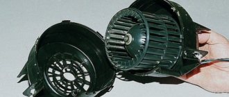
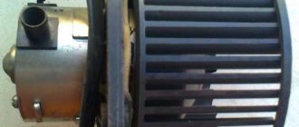
Fan
The air flow is created by a squirrel wheel fan driven by an electric motor. These two elements are enclosed in their own separate housing, installed on top of the heater housing. Moreover, it is structurally designed to provide the easiest possible access to the electric motor, since it is considered one of the weakest components of the system.
The design provides three modes of fan operation. This allows you to select optimal air supply conditions (cold or hot).
Control mechanism
Video: Useful tips for cars. Why does the VAZ stove not work?
To control the stove and redirect air movement and open and close the coolant supply valve, a control mechanism located on the center console is used. It consists of a three slider mechanism and a fan operating mode switch.
Equipment diagram for VAZ-2109 injector
The VAZ 2109 wiring for the injector has many connectors for connecting sensors to the computer.
- TPS (throttle position sensor);
- DPKV (crankshaft position sensor);
- DT (temperature sensor);
- DSA (vehicle speed sensor);
- Canister purge valve;
- MAF (mass air flow sensor);
- DD (knock sensor) and others.
The weak point of the harnesses is the power wiring on the bottom shelf of the radiator, which is constantly exposed to high temperatures and in this place it is in no way protected from water and dirt. Another problem is a harness under the carpet next to the driver's seat. Moisture constantly accumulates there, and in order to remove it, you need to dry the floor, inevitably tugging on the rope.
Since the mid-90s, VAZ 2109 began to use engines with an injection system, which greatly changed the electrical layout of the engine compartment and instrument panel. Below is an electrical diagram of a 1999 car with an ECM type GM ISFI-2S and January 4/4.1.
- 1 - nozzle system;
- 2 - candles;
- 3 — ignition control module;
- 4 — diagnostic connector;
- 5 — General Motors or January controller;
- 6 — connector for connecting the instrument cluster;
- 7 — main relay of the system;
- 8 — fuse for power supply wiring of the controller and ignition system module;
- 9 — protection of the speed sensor and air flow meter circuits;
- 10 — fuel supply pump power protection;
- 11 — fuel pump controller;
- 12 — engine temperature meter;
- 13 — idle system;
- 14 — detonation meter;
- 15 — tank purge system for collecting fuel vapors;
- 16 — crankshaft position meter;
- 17 — speed meter;
- 18 — air flow meter;
- 19 — lambda probe;
- 20 — throttle position angle meter;
- 21 — electric fuel pump complete with fuel level sensor;
- 22 — connection of the ignition system;
- 23 — control lamp;
- 24 — ignition switch;
- 25 - switching block;
- 26 — radiator cooling fan.
Since 2002, all VAZ 2109 began to be equipped only with engines with an injection system. The diagram shows the electrical wiring harness for the Bosch MP7.0 ECM (Euro 2 standards) on a 2003 car with a VAZ 2111 engine.
- 1 — four nozzles;
- 2 — spark plugs 2109;
- 3 — ignition distribution module;
- 4 - diagnostic connector, led into the car interior;
- 5 — Bosch controller connector;
- 6 — connector for the combination of lamps and instruments;
- 7 - main switching device of the system;
- 8 — fuse-link of the main device;
- 9 — controller for controlling the parameters of the fan on the cooling radiator;
- 10 — fan controller fuse;
- 11 — fuel pump control relay;
- 12 — fuel pump wiring fuse;
- 13 — intake air flow sensor;
- 14 — throttle opening angle sensor;
- 15 — engine temperature meter;
- 16 — regulator of idle speed parameters;
- 17 — sensor for measuring detonation in cylinders;
- 18 — crankshaft position sensor;
- 19 — lambda probe;
- 20 — immobilizer control unit;
- 21 — immobilizer status indicator;
- 22 — speed sensor;
- 23 - electric motor for driving the fuel pump; in the same module there is a device for measuring the remaining fuel in the tank;
- 24 — purge valve for the gasoline vapor recovery system;
- 25 — connector of the ignition system braid;
- 26 — instrument cluster with Check Engine indicator and warning lamp;
- 27 — ignition system start relay;
- 28 - lock;
- 29 — installation and switching block;
- 30 - cooling system fan.
Replacing the heater motor on a VAZ-2108-2109
The fan (motor) of the heater provides airflow to the car and increases the efficiency of the heater. If it malfunctions, the quality of interior heating deteriorates significantly. Extraneous sounds may appear that distract you from the road and are very annoying. The only way out is to repair or replace the failed unit. As a rule, car enthusiasts immediately go to a service station and shell out considerable sums for performing such work. For what? As a rule, changing the heater motor on a VAZ-2108-2109 is a matter of 30-40 minutes.
Basic faults
The first thing to do is figure out the reason. Start the car, switch the heater to different speed settings and listen to the sounds of the motor. If after turning on the blower no action occurs and no sound appears, then the fan simply does not work.
If the motor starts only at third speed, the cause of the malfunction may be the resistor installed in the switch (such a malfunction occurs quite often on VAZ cars).
Let's figure out what could be the reasons for the stove failure. There are several of them:
- The fuse has failed. The first thing you should do is check the integrity of the fuse that powers the heater fan. The cause of the device failure may be a small short circuit. Please note that one fuse link can power not only the motor, but also the clutter lighting, heated mirrors and other devices. Therefore, if the stove fails, check the functionality of other devices.
- Poor contact in the mounting block. This problem is common both in domestic cars and among foreign cars. The problem can be corrected by simply cleaning the contact group or pulling the contact.
- Ignition relay malfunction. The control device tends to stick. In this case, the heating system fan will turn on only when the engine is warm. If the malfunction manifests itself in this way, then it is advisable to immediately check the relay and, if necessary, install a new one.
- The airflow turns on only when you switch to third speed. Here you need to know the design of the device. The bottom line is that the first and second positions involve connecting additional resistance. At the third speed, switching occurs directly. Therefore, the fault can be eliminated by simply replacing the resistor.
- The switch is broken. Often the switch itself can be the cause of problems. To check it, you should use a regular 12-volt light bulb with wires soldered to it. Proceed in the following sequence:
— turn off the central part of the console to gain access to the switch (nothing should stop you from performing the check);
- start the car and connect one of the wires to the negative (car body). Use the second wire to alternately touch the output of the first, second and third speeds.
Now take stock. If the lamp lights up in all cases, then the switch is operational. If the light does not light, then move the wire to the “plus” of the switch. If the lamp does not light up here, we can conclude that there is a break in the motor circuits or a failed fuse;
- fan failure. If the switch is working properly (voltage is supplied) and the motor itself does not show any signs of “life”, then the cause of the problems may be the poor quality of the contact connection at the “minus”. The second option is to flood the motor brush.
Operating principle and causes of malfunction
Let's take a quick look at how the heating system generally works. To adjust the temperature, you open or close the tap of the heating device. After this, well-heated coolant begins to flow into the radiator, which is a source of heat (on a warm engine, the coolant temperature can be 90-95 degrees Celsius).
By switching the speed modes of the fan motor, you can set the speed of its operation. The volume of warm (cold) air entering the cabin directly depends on this. It all depends on the position of the tap - whether it is open or closed. In the future, using panel dampers, you can regulate the air supply and direct it throughout the cabin - to the windshield, legs and into the cabin, and so on.
Features of replacing the stove on a VAZ-2108-2109
So, if strong squeaks, squeals or complete failure of the fan appears, it needs to be replaced. This is done in the following sequence:
- Prepare the necessary tools - a 10mm socket, a Phillips screwdriver and a handle with a ratchet.
- Open the hood of the car and unscrew the five screws that secure the plastic trim to the windshield. Remove it completely and set it aside.
- Pull out the hood seal (it will also interfere with operation).
- Pull out the protective casing, behind which the fan motor itself is located.
- Unscrew the two mounting bolts that secure the motor to the car body.
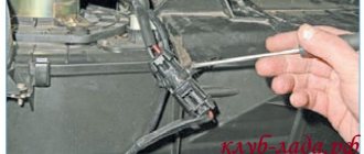
- Get into the passenger compartment and under the instrument panel on the driver's side, find the positive fan wire and discard it. Here you will find the “minus”, which is fixed with a nut - unscrew it using a ratchet handle and a suitable socket on “10”. There is no other way to turn off the voltage from the motor, because the power wires are directly soldered to the device.
- Remove the engine (to do this you will have to twist it a little to choose the optimal position).
- Make repairs if possible. If you don’t have the time and the necessary knowledge, just replace it.
- Install a new motor and return all parts in reverse order.
Conclusion
Thus, if the stove motor fails or unnecessary sounds appear, you should not endure and freeze - take some personal time, carry out a small diagnosis of the malfunction and fix the problem by repair or replacement. Good luck.
Relay and fuse box diagram 2109
The fuse blocks do not depend on the fuel injection system used - carburetor or injector. BP will differ only by year of manufacture of the car. That is, the mounting blocks for the carburetor and injector are the same. The VAZ 2109-099 fuse box (carburetor, injector) is located under the hood, in the compartment in front of the windshield on the left side.
Fuse block 2114-3722010-18
K1-relay for turning on headlight cleaners; K2-relay-breaker for direction indicators and hazard warning lights; K3 - windshield wiper relay; K4-relay for monitoring the health of lamps; K5-power window relay; K6 - relay for turning on sound signals; K7-relay for turning on the electric heating of the rear window; K8-relay for high beam headlights; K9-relay for low beam headlights; F1-F16 - fuses.
Fuse block 2114-3722010-60
K1 - Headlight wiper relay, K2 - Turn signal and hazard warning relay, K3 - Windshield wiper relay, K4 - Brake light and parking light relay, K5 - Power window relay, K6 - Horn relay , K7 - Rear window heating relay, K8 - Headlight high beam relay, K9 - Headlight low beam relay, F1 - F16 - Fuses, F1 - F20 - Spare fuses.
Attention! The power terminals on the generator often become loose, heat up, spark and melt the wiring. Pay attention to this point when searching for possible faults yourself.
Electrical diagram - wiring of a VAZ 2109 car with a carburetor engine and a low instrument panel (torpedo).
A - the order of conditional numbering of plugs in the ignition switch block of VAZ 2109 electrical equipment. B - the order of conditional numbering of the plugs in the block of the electric motor of the windshield wiper of the VAZ 2109.
Picture of the VAZ 2109 electrical circuit:
Table of decoding of the VAZ 2109 electrical circuit:
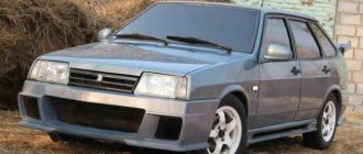
Features of the stove operation and its modification
VAZ 2109 interior heating
Owners of a VAZ 2109 car are often concerned that over time the stove begins to heat poorly. Needless to say, driving in such a car will no longer be comfortable. In such cases, only upgrading the stove can solve the problem.
Refinement methods
There are many ways to modernize a stove. Below are a few of them.
Damper control lever
- You can simply tighten the heater damper control cable to solve the problem. Make 1-2 turns of the cable located on the damper control lever (the lever itself is located on the stove body, near the gas pedal).
Note. The joints of the air ducts and the edges of the heater damper are covered with foam rubber, which does not compress completely. In this regard, a gap of several millimeters is formed, and the damper does not close completely. The above method will help you adjust the lever properly.
- There is another way to get to the control lever. There is a place on the driver's side and you need to try to reach with your hand and pull the lever, always with the heater fan on. During the adjustment process, the left ear will be in the area of the air duct nozzle and thus it will be possible to hear how the sound of the escaping air changes.
Heater valve
The reason for the ineffective operation of the heating system can also be incomplete opening of the stove faucet. This problem, by the way, occurs in almost all front-wheel drive cars of the VAZ family.
- The solution to the problem can be to tighten the valve control cable and then adjust the control lever to the maximum open position.
Note. In this case, it is possible that the valve will no longer close completely. But this is not the problem, but the fact that after adjusting the lever, the damper may lose its tightness and begin to leak (seen in the photo). In this case, we can recommend wrapping the leak area with a cloth that has been soaked in sealant and fixing it all with cold welding.
Heater valve leak location
Air ducts
Poor functioning of the heating system may be caused by leaky air ducts. The air that is pumped by the heater fan partially goes into the cracks, and the air flow thereby weakens and cools.
- The solution could be complete sealing and gluing of the connections that are located in the places where air flows from the stove to the outlet.