Hello again:)
Today I will tell you about eliminating the parasitic operation of the turn relay when turning on the high beam and instrument panel lights.
This parasitic effect appeared after installing a new turn relay 6422.3747 and an alarm button. Those. a long time ago. but since I very rarely drove at night, and almost never used the long-distance vehicle, the elimination of this problem was delayed for several months...
But finally I got to this notorious stick. After looking at the solution to the problem on the Internet, I realized that under certain conditions contact 3 of the relay receives a positive signal and it clicks, but the turns do not blink. The solution is quite simple, you need to take a regular 10A diode and place it in such a way that the current runs from contact 3 of the relay to the turn indicator light.
I didn’t finish adding the new relay, since the cause of the frequent blinking was eliminated and now I can fully experience the full usefulness of the feature with the blinking of turns turning more frequently :) The light bulb burned out - a good relay will immediately inform you about this, CONVENIENT :)
Thank you for your attention, Until Future Victories Friends :)
PS Last week I had to deal with an old-style VAZ 2109 mounting block, so one of them had to be changed; stupidly, the control contacts in the block were mixed up, you insert a relay, and it works like a jumper, i.e. without a button, the second block turned out to be suitable. But do you see this?
PSS Is this a spare tire? O_o
Many thanks to this resource. This is the primary source of the article dedicated to the “accident in the VAZ 2101”, everything else is blatant copy-paste or blatant use of materials without a link!
Recently, LED automobile lamps have become used. They are more durable and consume less current. The latter precisely affects the operation of the turn relay, changing its frequency. The frequency of relay operation is tied to the load resistance, that is, to the installed lamps. As the load resistance increases, which is exactly what happens when one of the lamps burns out or opens, the relay begins to operate most often. The same effect is observed when installing LEDs in direction indicators, since their power consumption is less, which means the resistance is much greater.
After studying the material in this article, you will be able to modify the standard turn signal relay for LEDs so that it operates at the frequency you need.
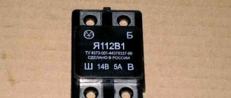
First of all, a little about the standard relay. The 3-pin turn signal relay which will be discussed is installed on cars starting from VAZ 2108 to the present, that is, on VAZ 2109, 2110, 2111, 2112, Lada Priora, Lada Kalina, GAZ cars. Marking 495.3747-ХХ.
To modify the relay, it will be necessary to open the housing. To do this, take a flat-blade screwdriver and remove the housing cover by pulling the plastic latches from two opposite sides.
Now let’s figure out what is responsible for what in this circuit and how we can change the operation so that with increased load the frequency of operation of the direction indicators does not change. The first is connection. Ground is connected to pin 31. 49a - output to lamps, 49 - input “+” from the turn signal switch.
P O P U L A R N O E:
Using inexpensive and accessible chips NE555, LM3915 and 7805, you can make a simple engine speed tachometer for a car using 10 LEDs.
The LED tachometer can be used for a car with an on-board voltage of 12V or 24V.
Not all cars are equipped with electronic voltmeters. And this is quite a necessary device in a car. It allows you to monitor the charging and condition of the battery. This is very important, especially in winter. Read more…
When I go out by car, I take my laptop with me...
One day I came across an article on an amateur radio website about how to make a car adapter for a laptop.
A simple circuit (see below) - one microcircuit and a pair of transistors...
All drivers are required to indicate maneuvers on the road by turning on the direction indicator. This flashing signal is found in every car. Its operating mode creates a turn relay, the circuit of which supplies current to the light bulbs and causes them to blink. At the same time, an audible signal sounds in the form of clicks, reminding you that the direction indicator is on. All these actions are provided by a special turn relay circuit.
Among various designs, electromagnetic-thermal and electronic relays are most widespread. The latest devices are considered more modern and are installed on all later car models.
How does an electromagnetic-thermal relay work?
These devices are no longer used in modern cars. However, in older models they are still widely used.
The design of the electromagnetic-thermal relay is quite simple; it uses a circuit for connecting turn signals through an electromagnetic-type relay. It is made in the form of a cylindrical core, and a thin copper wire is used as its winding. At the top of the core there are two groups of contacts, and metal anchors are installed on each side. The first group of contacts closes the circuit where there is a control light located on the instrument panel. With the help of other contacts, the circuit with the lamps in the direction indicators is closed. They are the ones who provide the flashing mode.
Electronic relay: circuit and principle of operation
The design of the electronic turn signal relay consists of two main parts. From a standard electromagnetic relay that performs switching and an electronic key that provides a certain frequency of operation of this device.
The nichrome string has been replaced with an electronic key. With its help, voltage is supplied and removed from the winding of the electromagnetic relay at certain intervals. The key is based on microcircuits or discrete elements. They are components of the master oscillator and control circuits.
The operating principle of an electronic relay is very simple. When voltage is applied to the relay, the master generator is switched on. With its help, control pulses with different frequencies are generated, which are supplied to the control circuits. By means of pulses, the current passing through the winding of the electromagnetic relay is supplied or interrupted. Such actions cause the anchor to alternately attract or lower. As a result, the contact groups close or open at a certain frequency, ensuring the same flashing of the signal lamps.
All electronic elements of the relay are mounted on a separate board. The electromagnetic relay is located above the board. Both of them are housed in a plastic case. The contacts are brought out from below or from the side. For fastening the housing there are holes and eyes for bolted connections.
What is a turn signal switch used for?
Traffic regulations indicate that each driver, planning to perform a particular maneuver, is obliged to notify other drivers of his intentions. Once upon a time, when cars were still a curiosity, such notifications were given with the left hand (when driving on the right). If the arm was extended, this meant the driver wanted to turn left when it was bent and the fingers were pointing up - to the right.
With the increase in the number of cars, traffic rules and lighting devices were improved, not only making it easier to move in the dark or in conditions of reduced visibility, but also signaling to other participants about a change or suspension of movement.
Traffic change signal
Cars began to be equipped with light direction indicators, which were supposed to pulsate to attract attention. To prevent the devices from constantly shining, but from blinking periodically, a small device was invented, which later became known as a pointer breaker or rotary relay. Despite the fairly large number of varieties of the mentioned device, their functions are similar: supplying a pulsating impulse to the turn signal lamps and signaling with clicks that they are on.
Turn signal relay pinout
During operation, the standard turn relay may fail and in this case it needs to be replaced. Incorrect operation of the device becomes noticeable, especially when the control light stops lighting up. The main cause of the malfunction is incomplete closure of the device.
In other cases, the relay begins to function unstably, and the relay contacts close at different time intervals. In some cases, the volume level of the sound accompanying the operation of the device is significantly reduced. This can create a serious problem on the road when the device is activated without the driver noticing due to accidental contact while driving the vehicle.
These shortcomings are eliminated by replacing the standard device with an electronic design. In this case, the turn signal relay is connected according to the standard diagram shown in the figure. Pin No. 1 is positive, the second pin connects to the turn switch, the third connects to the warning light, and the fourth connects to ground.
All connections and contacts must be reliably insulated using electrical tape and cambric, which is a hollow plastic braid. This eliminates possible short circuits with other conductors. Certain inconveniences are created by the plastic housing of the electronic relay, which does not always fit in its standard location. However, home craftsmen quite easily overcome this difficulty and find the most optimal technical solution.
Causes of malfunctions
Malfunctions of the turn relay are usually associated with a violation of the electromagnetic patency in the relay itself. The cause may be burnt or shorted contacts, swollen capacitors, failure of the electronic circuit, etc. Typically, the cause of relay failure can be identified by the characteristic manifestations of the malfunction.
- If the turn signals are constantly on and do not blink, then most likely the cause of the malfunction is a breakdown of the electromagnetic part of the relay. Most often, this is due to shorted contacts due to their burning.
- Unusual blinking of the turn signals (too fast or too infrequent) may also be due to the turn signal relay. However, in this case, you can look for the problem in other places. Possible reasons for this behavior of the indicators may lie in oxidation of the lamp socket or base, or a break in the wire going to the lamps. This phenomenon also often occurs after replacing standard incandescent lamps in direction indicators with LEDs. If none of these possible reasons is confirmed, then, most likely, the breakdown still lies in the relay.
- Another option for incorrect operation of the turn relay is that the indicator lamps do not light up at all. This phenomenon occurs when the relay contacts burn out. However, this manifestation of a malfunction is also typical for other breakdowns: a blown fuse, an open circuit or a broken turn switch.
DIY turn relay
Sometimes situations arise when the standard turn signal relay fails and it is not possible to purchase a new device. In such a situation, you can try to make a turn signal relay with your own hands to provide the car with the necessary signals. The simplest electronic devices that you can create yourself are simple and easy to use, operate smoothly and reliably. High accuracy is achieved through the use of PWM controllers used in all circuits.
The simplest replacement for an electromagnetic relay is designed for a maximum load power of 150 W. It is connected to the positive terminal. If the IRFZ44 field switch is replaced with the IRF3205 model, then 200 W can be connected. This simple circuit ensures high accuracy of operation. The blinking frequency does not depend on the power of the light bulbs, so LED, halogen and other lamps can be included in the circuit.
The frequency of flashing is directly related to the capacitance of the capacitor. As the capacity increases, the light bulb will blink more rarely, and, conversely, decreasing the capacity will lead to faster blinking. The low-power 1n4148 diode can be replaced by any similar element. When the circuit reaches a power of 80 W, a slight generation of heat is observed in the field-effect transistor area. This means it is ready to use.
There is another simple circuit of a turn relay with a coil - simple, reliable and inexpensive. It is capable of lighting both regular light bulbs and LED ones and is designed for 12 V. The contacts are connected according to the principle of a regular switch, that is, in series with the light bulb. The LED is installed in the circuit as an indicator during commissioning work. The device parameters are adjusted by changing the resistance of the resistor.
Turning relay VAZ 2101 replacement with an electronic relay.
If desired, you can replace the electromagnetic-thermal relays of the VAZ 2101 with an electronic relay used on VAZs of subsequent brands. The connection is made in almost the same way. In addition to the standard wires, it is necessary to add only one wire connecting the electronic relay to the vehicle ground. In this case, you can also connect an alarm button.
admin 26/11/2013
“If you notice an error in the text, please highlight this place with the mouse and press CTRL+ENTER” “If the article was useful to you, share the link to it on social networks”
Repair and replacement of turn signal relays
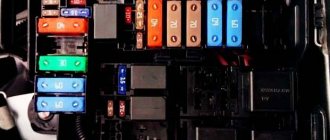
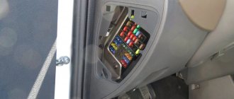
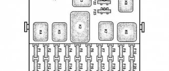
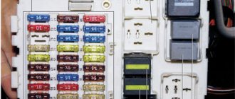
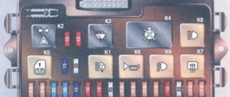
First, you need to decide where the turn signal relay is installed. In some cars it can be found right behind the dashboard - it is located a little to the right. In other cars, the relay is installed directly in the mounting block
. If you are not sure where exactly the device is located and how it is attached, prepare the following tools:
- Key head set to “10”;
- Pliers;
- Crosshead screwdriver;
- Plastic puller.
Once the relay has been removed, check the condition of the wiring and contacts. If you want to repair the relay, you need to do the following:
- Clean the contact plates from carbon deposits. Often this can be done with a piece of an ordinary eraser;
- Note the metal U-shaped bridge. If it is covered with a thick layer of carbon deposits or even broken, it will have to be replaced. As practice has shown, several cores from a copper cable can be soldered in its place;
- If you see cracks in the power leads, they need to be soldered. In case of broken contacts, soldering will also be a solution.
If you are serious about repairing an old relay, then you will need a donor relay with the same characteristics. Moreover, a relay accidentally found in a store will not work. You will have to find technical documentation of the original device and a suitable donor. Unfortunately, much information about relay repair, as well as technical documentation, can only be found on English-language sites. First of all, you should be interested in such a column as “ Characteristics
” and its following points:
Contact Rating
;
all 3 parameters Max.
switching ;
Operate Time
;
both Endurance
;
Initial Insulation Resistance
.
Also take a look at the Coil Data
. The more matches there are with the parameters of the failed relay, the longer it will last after repair using donor components. We also note that if you want to adapt an existing relay for use in a circuit with LED turn signals, you cannot do without soldering. In this case, the best solution would be to cut the current measuring circuit and solder an additional multi-turn resistor, although you can get by with a regular shunt resistor - a suitable one will be more difficult to find, but it will also work.