Repairing engine 21126 VAZ 2170 Priora after timing belt break
Today we brought one of the old clients to the Priora, as it turned out, the jammed pump broke the belt and, as a result, the valves were bent.
But progress at AvtoVAZ does not stand still, and if on the engines of the tenth family the valves were simply bent, then on the Priora 126s the connecting rods also lose alignment and, if they are not changed, there is a high probability that the engine will begin to eat oil and, accordingly, your money. Glory to the designers of AvtoVAZ!
But every cloud has a silver lining, there are sets of pistons for 126 engines with grooves that do not bend the valves. In this article we will describe the procedure for repairing the cylinder head after a broken timing belt, as well as replacing the piston. Removing and installing the timing belt is described in this article, so we will not dwell on it in detail.
To perform this procedure, torque wrenches are required!
Replacing the cathode collector gasket on a VAZ 2170 2171 2172 Lada Priora [edit]
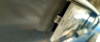
Between the flanges of the cylinder head and the catalytic collector there is a sealing gasket made of two thin molded metal strips connected by spot welding.
If the gasket is leaking, exhaust gases break out, accompanied by a characteristic sharp sound. If the malfunction cannot be eliminated by tightening the catalytic converter fastening, replace the gasket. 1. Disconnect the wire from the negative terminal of the battery.
3. Disconnect the exhaust pipe of the additional muffler from the exhaust manifold, for which unscrew the nuts securing the exhaust pipe flange to the exhaust manifold flange, disconnect the suspension cushions from the muffler brackets and remove the exhaust pipe flange from the studs of the exhaust pipe flange of the Lada Priora. Remove the additional muffler (see “Replacing the additional muffler”).
5. ...and disconnect the wiring harness blocks of the control and diagnostic oxygen concentration sensors from the engine harness.
7. ...and disconnect the holders of the wiring harnesses of the control and diagnostic oxygen concentration sensors from the heat-insulating shield of the Lada Priora steering mechanism.
9. Using a 10mm wrench, unscrew the three nuts securing the thermal insulation shield of the steering mechanism to the engine shield (two nuts are located under the steering mechanism)…
11. Using a 13mm wrench, unscrew the two nuts securing the bracket for the water pump supply pipe...
13. Using a 13mm wrench, unscrew the eight nuts securing the catalytic collector to the priority cylinder head...
15. ...and its gasket.
17. Check the flatness of the flange surface of the Priora catalytic collector. To do this, place the ruler with its edge on the surface of the flange and measure the gap between the flange plane and the ruler with a feeler gauge. Grind the flange surface or replace the catalytic collector VAZ 2172 if the gap exceeds 0.1 mm.
- Useful tips
To prevent the gasket from sticking and to improve its tightness, we recommend lubricating the gasket on both sides with a thin layer of graphite grease before installation.
Let's start to disassemble
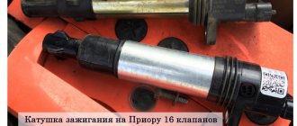
First, drain the oil and antifreeze. We remove the protective cover, the air filter with pipes, disconnect the ignition coil connectors, the throttle cable and the throttle assembly.
We remove the thermostat housing and simultaneously disconnect all the available connectors and pipes. We remove all the wiring that was in our way towards the battery.
We remove the generator. We unscrew the eight thirteen nuts holding the intake manifold and remove it. We unscrew all the bolts securing the valve cover, as well as the side engine support.
Unscrew the eight nuts and remove the exhaust manifold.
Remove the timing belt, camshaft pulleys and pump.
In three passes, so as not to deform the part, we first loosen and then unscrew twenty bolts of the camshaft bearing housing, the head is eight.
Be sure to follow the sequence shown in the photo.
Remove the bearing housing. We remove the camshafts; there is a distinctive lip on the intake camshaft.
Also, in several passes, we first loosen and then unscrew the ten cylinder head mounting bolts.
Be sure to follow the sequence shown in the photo.
Remove the cylinder head. All sixteen valves are replaced.
Replacing the oil pan gasket on a VAZ 2170 2171 2172 Lada Priora [edit]
If oil leakage through the oil pan gasket cannot be eliminated by tightening its mounting bolts, it means that the gasket is severely deformed and must be replaced. Perform the work on an inspection ditch, overpass, or, if possible, on a lift.
1. Remove the Lada Priora engine mudguard (see “Removing and installing the Lada Priora engine mudguard”).
3. Using a 10mm wrench, unscrew the bolts securing the front cover of the clutch housing...
5. Using a socket head, unscrew the sixteen bolts securing the Lada Priora oil sump.
7. Remove the crankcase gasket from the mating surface of the cylinder block.
9. Place a new gasket on the mating surface of the Priora oil sump.
Helpful advice
In order to fix the gasket on the crankcase, apply a layer of sealant to its mating surface and glue the gasket to it. In addition to fixation, the sealant will provide better tightness of the connection. For the same purpose, we recommend applying sealant to the mating surface of the cylinder block.
11. Fill the engine crankcase with oil.
Cylinder head repair
We mark all hydraulic compensators with numbers using an ordinary clerical touch and put them away. An ordinary magnet will help you pull them out. We dry out the valves and remove the oil seals (valve seals), the valves into scrap metal, the oil seals into the trash. We clean all channels. We take the head for grinding, just in case. After washing it again with kerosene after sanding and blowing it with air, we begin to assemble it.
We arrange the recently purchased valves in the sequence in which they will be located in the cylinder head and begin to grind in one by one. Lubricate the valve stem with clean oil and apply lapping paste to the edge.
We insert the valve into place and put a valve grinding tool on the valve stem. The stores sell a device for manual lapping, but since this is the twenty-first century, we are mechanizing the process. We take the old valve and cut off the rod from it, select a rubber tube for it of such a diameter that it fits tightly. The rod is in a reversible drill, one end of the tube is on it, the other is on the valve being ground in. At low speeds we begin to grind the valve, constantly change the direction of rotation and periodically press it to the seat or weaken the force. On average, the valve takes about twenty seconds. We take it out and wipe it.
The valve is considered ground in if a uniform gray strip of at least 1.5 mm wide appears on the chamfer.
The same stripe should appear on the valve seat.
Video of manually grinding valves
For a sixteen valve head, everything is the same, only there are twice as many valves.
After lapping, all valves and seats are thoroughly wiped and washed with kerosene to remove any remaining lapping paste. We check for leaks.
We tighten the old spark plugs and put all the valves in place. Pour kerosene and wait three minutes, if the kerosene does not run away all is well, otherwise we grind the valves on this cylinder. We had to grind four valves again, after which the kerosene stopped flowing.
We stuff new valve seals.
We put the valves in place and dry them.
Before doing this, lubricate the valve stems with clean oil.
After lubricating it with clean oil, we put the hydraulic compensators in place and, covering them with a clean cloth, remove the head out of sight. We're done with the cylinder head.
Why are guide bushings needed?
Before installing the cylinder head, perform the following steps: clean the threaded holes, as well as all holes for the bushings (photo 1). Each bushing is installed in place, and only then a gasket is placed on top.
Everything is ready to install the cylinder head
Metal parts adjacent to the gasket must be degreased. We looked at the cylinder head tightening diagram, but the cylinder head itself must be installed correctly:
- We place the cylinder head on the cylinder block;
- By moving the part in different directions, we ensure that the bushings fit into the recesses.
After “step 2” the screws can be tightened.
Sealant
No sealing compounds are used when installing the gasket! Solidol, CIATIM and other lubricants are not even needed. The main thing is that the metal must be degreased. And the cylinder head gasket must be new.
Cylinder head cover and tightening order of its bolts
The metal cover installed on the cylinder head must not allow air to pass through. At points of contact with other parts, tightness must also be maintained. Therefore, sealant is applied to the edge of the lid. An example is shown in the photo.
Cylinder head cover before installation
Here you need to use materials: Loctite-574, ANACROL, etc. The screws on the cover are tightened with an “8” key.
Recommended screw tightening torque
The recommended screw tightening torque is only 3-4 N*m. Don't be surprised: the sealant will do its job. You just need to let it dry after putting the cover in place.
You can unscrew the screws in any order. Their number is 15 or 14. When installing, it is better to follow the sequence shown below.
The order of tightening the cap is marked with numbers and arrows
There is usually no need to replace the screws - the load is too small. We wish you success.
Common Misconceptions
If the bolts are pulled out too much, they are tightened in four steps. At “step 2” the tightening torque will be 70-85 N*m. All of these are common misconceptions that do not apply to 16-valve internal combustion engines.
All steps in one video: replacing the cylinder head gasket
Didn't find the information you are looking for? on our forum.
Let's move on to the cylinder block
We remove the pallet. Rotating the crankshaft as it is convenient for us, unscrew two bolts on each connecting rod cap. We use a TORX E10 head for this.
We take out the pistons along with the connecting rods. To do this, use the wooden handle of a hammer to press the connecting rod from below and lightly tap it to knock it up. We remove the old liners and buy new ones of the same size according to the markings on them. Here is another stone in AvtoVAZ’s garden, the owner has never climbed into the car from the interior or into the engine, but three pistons were of group “B” and one was “C”. It turns out that at the factory they re-sharpened one cylinder a little and simply put an enlarged piston there, no words. There are no options, we take group “C”, don’t sharpen the engine because of this. We will not touch the main liners either.
We buy a new piston group that does not bend the valves, connecting rods and connecting rod bearings.
Eliminating longitudinal play of the crankshaft
It was noticed on this motor. To eliminate it, replace the thrust half-rings. Standard and repair sizes are available. We take the first repair size, if they are too tight we sand them down a little. We unscrew the middle main bearing and gently push it with a screwdriver and move the half rings. The mark on it is in the form of three serifs, shown below.
Engine assembly
We wipe the crankshaft journals, cylinder bores and connecting rod bearing seats with a clean rag; by the way, they can also be degreased. We put new liners into the connecting rod and the cover, so that the antennae of the liners fit into the grooves.
Lubricate the bearings, crankshaft journals and cylinders with clean oil. We unfold the piston rings with locks as shown in the figure, the angle between them should be 120 degrees.
We put a mandrel on the piston to compress the rings, having previously lubricated it inside with clean oil. Not forgetting about the direction, the arrow on the piston should be directed towards the front of the engine, we place it in its cylinder.
We turn the crankshaft so that the connecting rod journal is at the very bottom. Gently tapping the wooden handle of a hammer pushes the piston into the cylinder. We remove the mandrel and push the piston down until the connecting rod sits on the crankshaft. We put the connecting rod bearing cap on the bottom, remembering the marks.
Tighten the connecting rod cover mounting bolts to a torque of 5 kgf*m.
We also repeat with all the other cylinders.
We put back everything that we removed from below. We blow through the top and clean the holes for the cylinder head mounting bolts. We install a new cylinder head gasket and the head itself. Lubricate the bolts with a thin layer of oil, most importantly without fanaticism. We tighten the bolts in several passes in the reverse order of unscrewing, see photo at the beginning of the article. The tightening sequence is as follows:
We install hydraulic compensators, camshafts and camshaft bearing caps. Lubricate all rubbing surfaces with clean oil. Before installing the camshaft bearing caps, lubricate the perimeter and rims around the spark plug wells with a thin layer of sealant.
We tighten the bearing cover bolts in the reverse order of unwinding, with a torque of 2 kgf*m, see photo at the beginning.
Well, then we install all the parts in the reverse order of removal. We fill in all the fluids and start it, it may not start right away, this is normal. When you first start it will smoke well until the oil on the cylinders burns, make sure the oil pressure light goes out. Let it run for a minute and turn it off, and suddenly see where something is leaking. We start it several more times, constantly increasing the operating interval, bring it to operating temperature, constantly checking the oil and antifreeze, and also pay attention to the fact that no extraneous noise appears. Let it rest for an hour and then idle again for about an hour, constantly monitoring the temperature. Well, then the break-in, if you sharpened it, if not, then you can drive only the first thousand kilometers, try not to raise the speed above 3000, and not tow it.
Source
Video “Cylinder head repair and configuration”
This video talks about repairing the cylinder head of a Lada Priora.
Comment
The cylinder head can be removed as an assembly with camshafts and thermostat (to access the connecting rod and piston group, to replace the gasket, etc.). If the head is subject to repair, it is advisable to disassemble it as much as possible before removing it from the cylinder block.
To complete the job, you will need an inspection ditch or overpass, as well as a new cylinder head gasket.
Removal
1. Drain the coolant from the engine.
Recommendation
If the connecting rod-piston group is to be repaired, it is advisable to immediately drain the oil from the engine crankcase.
2. Remove the decorative trim of the engine.
3. Remove the bracket for the upper rod that mounts the power unit.
4. Using a 10 mm wrench, unscrew the bolt securing the ground wire tip and disconnect it from the block head. Disconnect the wiring block from the emergency oil pressure sensor.
5. To avoid damage, disconnect the wire block from the coolant temperature sensor.
6. Disconnect the thermostat housing from the cylinder head.
7. Remove the cylinder head cover.
8. Remove the camshafts.
9. We remove the hydraulic pushers from the mounting holes.
Sequence of loosening the cylinder head bolts
10. Remove the catalytic manifold.
Comment
The camshaft position and temperature gauge sensors do not need to be removed, but you must remove the head from the cylinder block carefully so as not to accidentally damage the sensors.
11. Evenly, in several steps, use a 10 mm hex key to unscrew the ten bolts securing the cylinder head.
12. Remove the head from the cylinder block.
13. Remove the cylinder head gasket.
14. To avoid losing it, remove the two guide bushings from the mounting holes in the cylinder block.
15. We wash the cylinder head from dirt and deposits with kerosene or diesel fuel.
Installation
1. Remove any remaining oil and coolant from the threaded holes of the cylinder block (under the cylinder head bolts).
2. Wipe the mating surfaces of the head and cylinder block with a cloth, degrease them with a solvent.
Warning!
Always use a new gasket when installing the cylinder head. Oil contact with the gasket surface is unacceptable.
3. Install the head guide bushings into the seats of the cylinder block. We place the gasket on the cylinder block, and the guide bushings should fit into the corresponding holes in the gasket.
4. Install the head on the cylinder block. By slightly moving the head from side to side, we ensure that the guide bushings fit into the corresponding recesses of the head.
Warning!
Reuse of cylinder head bolts is permitted only if their length does not exceed 100 mm.
5. Using a caliper or a bench ruler, measure the length of the bolts. Bolts longer than 100 mm are replaced.
6. Before installation, dip the threaded part of the bolts into engine oil, then let the oil drain, waiting for about half an hour.
7. Install the head mounting bolts into the holes of the head. Using a torque wrench, tighten the head mounting bolts in three steps - first with a torque of 20 Nm (2 kgcm), then turn the bolts by 90° and then turn the bolts by 90° again. In this case, we follow the order indicated in the photo (see above).
8. We perform further engine assembly in reverse order.
Cylinder head bolt tightening sequence
https://youtube.com/watch?v=ykLokuKk50k
Sources
- https://spike.su/index.php/cylinder head-Lada-Priora.html
- https://avtozam.com/vaz/lada-priora/remont-gbts/
- https://for-priora.ru/?p=665
practical guide
1. Remove the air filter.
2. Remove the decorative trim of the engine.
3. Remove the ignition coils.
4. Remove the intake module.
5. Using an 8 mm socket wrench, unscrew the 15 bolts securing the cylinder head cover and remove the cover.
6. Remove the cover. Comment
If necessary, use a 10 mm wrench to unscrew the fastening bolt and remove the bracket for fastening the injector wiring harness pads and ignition coils from the cylinder head cover. Also, if necessary, loosen the clamps and disconnect the hoses from the cover.
Flushing
1. Using an 8 mm wrench, unscrew the six bolts securing the oil deflector.
2. Using a slotted screwdriver, press out the clamps of the oil filler neck. 3. Remove the oil deflector from the cylinder head cover. 4. Rocking from side to side, remove the oil filler neck.
5. Wash the removed parts in kerosene and wipe with a clean cloth.
6. Assemble the block head cover in the reverse order. Tighten the bolts to a torque of 1.9-4.6 Nm (0.2-0.5 kgcm)
Warning!
Don't forget to install lock washers under the bolt heads.
Removing camshafts and replacing valve lifters
We carry out work to replace camshafts and valve lifters.
Remove the plastic engine cover. Using a Phillips screwdriver, loosen the clamp securing the main crankcase ventilation hose... ...and remove the hose from the cylinder head cover fitting. We remove the intake pipe (see “Removing the intake pipe”) and cover the channels in the cylinder head with a rag to prevent objects from getting into the engine. We remove the ignition coils (see “Checking the condition and replacing spark plugs”). Use a Phillips screwdriver to loosen the clamp securing the crankcase ventilation idle circuit hose...
...and remove the hose from the cylinder head cover fitting.
Using a 10mm socket, unscrew the bolt securing the block bracket for the wiring harness of the engine management system... ...and remove the bracket with the blocks from the cylinder head cover. Squeezing the petals of the plastic holder of the engine management system wiring harness with pliers...
...remove the wire harness holder from the bracket secured to the cylinder head cover. Using a “8” socket, unscrew the 15 bolts securing the cylinder head cover.
Location of the cylinder head cover bolts The cover is installed on a sealant, so...
... use a screwdriver to pry the lid off the tide...
...and remove it. To check the serviceability of the hydraulic pusher...
... use a screwdriver to press on the hydraulic pusher (when checking, the camshaft cam corresponding to the hydraulic pusher should be facing the pusher with the “back of the head”, that is, do not put pressure on the pusher). In normal condition, the hydraulic tappet should move in the cylinder head socket with significant force, compressing the valve spring. If the hydraulic pusher itself is pressed with little force, then it must be replaced. We check other hydraulic pushers in the same way. Remove the camshaft gear pulleys (see “Replacing camshaft seals”). We disconnect the wire block from the sensor for the low (emergency) oil pressure warning light in the engine (see “Removing the low oil pressure warning light sensor”). Using the “8” head, unscrew the 20 bolts securing the camshaft bearing housing.
Let's start to disassemble
First, drain the oil and antifreeze. We remove the protective cover, the air filter with pipes, disconnect the ignition coil connectors, the throttle cable and the throttle assembly.
We remove the thermostat housing and simultaneously disconnect all the available connectors and pipes. We remove all the wiring that was in our way towards the battery.
We remove the generator. We unscrew the eight thirteen nuts holding the intake manifold and remove it. We unscrew all the bolts securing the valve cover, as well as the side engine support.
Unscrew the eight nuts and remove the exhaust manifold.
Remove the timing belt, camshaft pulleys and pump.
In three passes, so as not to deform the part, we first loosen and then unscrew twenty bolts of the camshaft bearing housing, the head is eight. Be sure to follow the sequence shown in the photo.
Remove the bearing housing. We remove the camshafts; there is a distinctive lip on the intake camshaft.
Also, in several passes, we first loosen and then unscrew the ten cylinder head mounting bolts. Be sure to follow the sequence shown in the photo.
Remove the cylinder head. All sixteen valves are replaced.
Cylinder head repair
We mark all hydraulic compensators with numbers using an ordinary clerical touch and put them away. An ordinary magnet will help you pull them out. We dry out the valves and remove the oil seals (valve seals), the valves into scrap metal, the oil seals into the trash. We clean all channels. We take the head for grinding, just in case. After washing it again with kerosene after sanding and blowing it with air, we begin to assemble it.
We arrange the freshly purchased valves in the sequence in which they will stand in the cylinder head and begin to grind in one by one. Lubricate the valve stem with clean oil and apply lapping paste to the edge.
We insert the valve into place and put a valve grinding tool on the valve stem. The stores sell a device for manual lapping, but since this is the twenty-first century, we are mechanizing the process. We take the old valve and cut off the rod from it, select a rubber tube for it of such a diameter that it fits tightly. The rod is in a reversible drill, one end of the tube is on it, the other is on the valve being ground in. At low speeds we begin to grind the valve, constantly change the direction of rotation and periodically press it to the seat or weaken the force. On average, the valve takes about twenty seconds. We take it out and wipe it. The valve is considered ground in if a uniform gray strip of at least 1.5 mm wide appears on the chamfer.
The same stripe should appear on the valve seat.
Video of manually grinding valves
For a sixteen valve head, everything is the same, only there are twice as many valves.
After lapping, all valves and seats are thoroughly wiped and washed with kerosene to remove any remaining lapping paste. We check for leaks. We tighten the old spark plugs and put all the valves in place. Pour kerosene and wait three minutes, if the kerosene does not run away all is well, otherwise we grind the valves on this cylinder.
We had to grind four valves again, after which the kerosene stopped flowing.
We stuff new valve seals.
We put the valves in place and dry them. Before doing this, lubricate the valve stems with clean oil. After lubricating it with clean oil, we put the hydraulic compensators in place and, covering them with a clean cloth, remove the head out of sight. We're done with the cylinder head.
Engine assembly
We wipe the crankshaft journals, cylinder bores and connecting rod bearing seats with a clean rag; by the way, they can also be degreased. We put new liners into the connecting rod and the cover, so that the antennae of the liners fit into the grooves.
Lubricate the bearings, crankshaft journals and cylinders with clean oil. We unfold the piston rings with locks as shown in the figure, the angle between them should be 120 degrees.
We put a mandrel on the piston to compress the rings, having previously lubricated it inside with clean oil. Not forgetting about the direction, the arrow on the piston should be directed towards the front of the engine, we place it in its cylinder.
We turn the crankshaft so that the connecting rod journal is at the very bottom. Gently tapping the wooden handle of a hammer pushes the piston into the cylinder. We remove the mandrel and push the piston down until the connecting rod sits on the crankshaft. We put the connecting rod bearing cap on the bottom, remembering the marks. Tighten the connecting rod cover mounting bolts to a torque of 5 kgf*m. We also repeat with all the other cylinders.
We put back everything that we removed from below. We blow through the top and clean the holes for the cylinder head mounting bolts. We install a new cylinder head gasket and the head itself. Lubricate the bolts with a thin layer of oil, most importantly without fanaticism. We tighten the bolts in several passes in the reverse order of unscrewing, see photo at the beginning of the article. The tightening sequence is as follows:
We install hydraulic compensators, camshafts and camshaft bearing caps. Lubricate all rubbing surfaces with clean oil. Before installing the camshaft bearing caps, lubricate the perimeter and rims around the spark plug wells with a thin layer of sealant. We tighten the bearing cover bolts in the reverse order of unwinding, with a torque of 2 kgf*m, see photo at the beginning. Well, then we install all the parts in the reverse order of removal. We fill in all the fluids and start it, it may not start right away, this is normal. When you first start it will smoke well until the oil on the cylinders burns, make sure the oil pressure light goes out. Let it run for a minute and turn it off, and suddenly see where something is leaking. We start it several more times, constantly increasing the operating interval, bring it to operating temperature, constantly checking the oil and antifreeze, and also pay attention to the fact that no extraneous noise appears. Let it rest for an hour and then idle again for about an hour, constantly monitoring the temperature. Well, then the break-in, if you sharpened it, if not, then you can drive only the first thousand kilometers, try not to raise the speed above 3000, and not tow it.
Source
Requirements for sealant
When choosing a particular product, you first need to pay attention to its performance characteristics. As stated above, first of all you need to choose a sealant that can work in high temperature conditions . Therefore, the higher the temperature it can withstand, the better. This is the most important condition!
The second important factor is resistance to various aggressive chemical compounds.
(motor and transmission oils, solvents, brake fluid, antifreeze and other process fluids).
The third factor is resistance to mechanical stress and vibration.
. If this requirement is not met, the sealant will simply crumble over time and spill out from the place where it was originally placed.
The fourth factor is ease of use.
. First of all, this concerns packaging. It should be convenient for the car owner to apply the product to the work surface. That is, it is worth buying small tubes or cans. The latter option is more convenient and, as a rule, is considered professional, as it is used by service station workers.
If you do not plan to use it anywhere other than the valve cover, then buying a large package does not make sense for you (most sealants have a shelf life of 24 months, and the storage temperature is from +5°C to +25°C, although this information needs to be clarified in the instructions for a specific product).
When using such tools, you must remember the assembly technology. The fact is that many automakers include such sealing agents along with the cover gasket. However, when disassembling the engine (for example, overhauling it), the car owner or service technicians may not reapply the sealant, which will lead to oil leakage. Another possible reason for this is inappropriate tightening torque of the mounting bolts.